Rectifier circuit

a rectifier diode and rectifier technology, applied in the direction of emergency protective arrangements for limiting excess voltage/current, electric devices, pulse techniques, etc., can solve the problems of power loss at the rectifier diode, power loss directly affecting the fuel consumption of the respective vehicle, etc., to reduce the expenditure for cooling and reduce the effect of power loss

Active Publication Date: 2010-09-30
ROBERT BOSCH GMBH +1
View PDF17 Cites 24 Cited by
  • Summary
  • Abstract
  • Description
  • Claims
  • Application Information

AI Technical Summary

Benefits of technology

[0006]By contrast, a rectifier circuit having the features described herein has the advantage that the power loss is reduced, and for this reason, the expenditure for cooling may also be reduced.

Problems solved by technology

1 V. Therefore, especially in the case of the rectification of lower alternating voltages, power losses are created at the rectifier diodes.
In addition, the power losses directly affect the fuel consumption of the respective vehicle.

Method used


Image

  • Rectifier circuit
  • Rectifier circuit
  • Rectifier circuit

Examples


Embodiment Construction

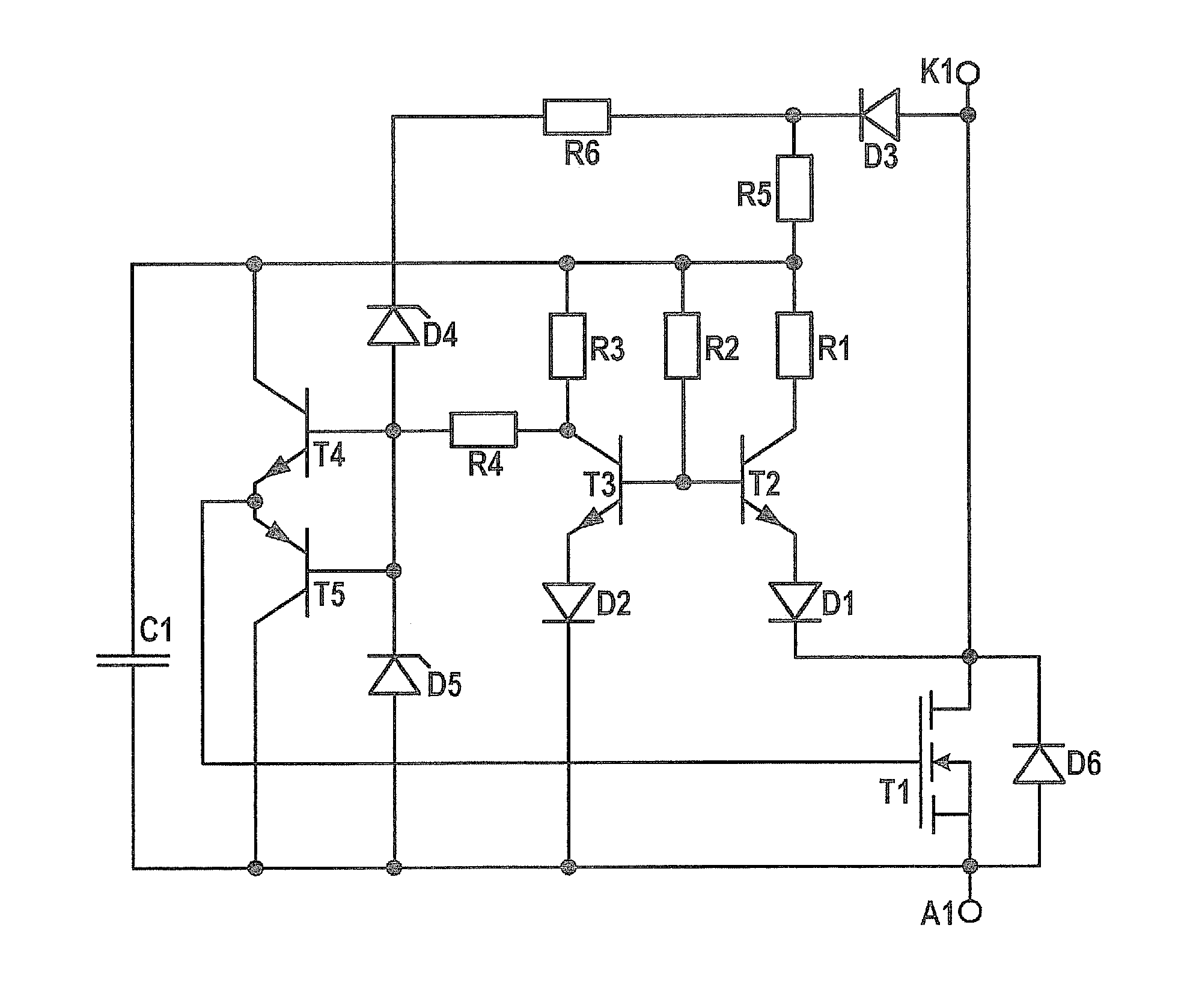
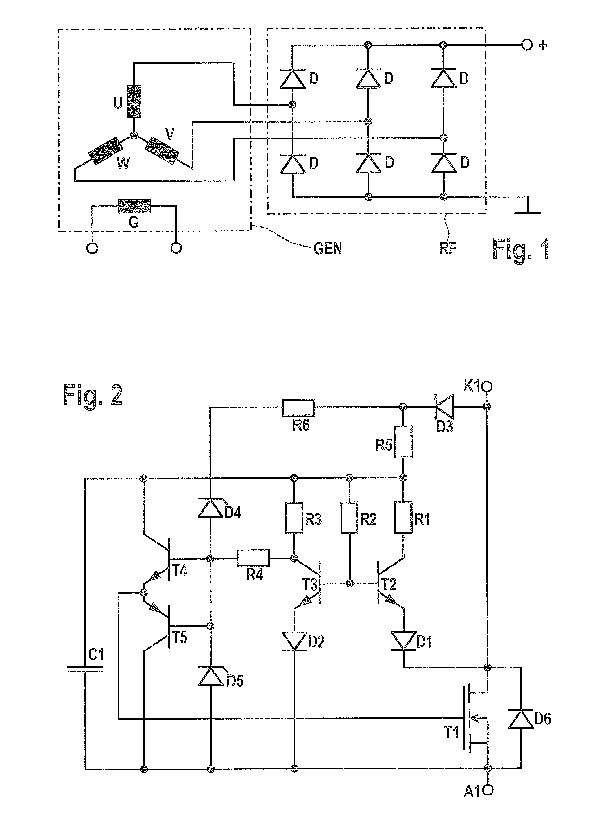
[0017]FIG. 2 shows a rectifier circuit according to a first exemplary embodiment of the present invention.

[0018]The rectifier circuit shown in FIG. 2 may be used, for example, in a rectifier bridge instead of a silicon p-n diode. It has a cathode terminal K1 and an anode terminal A1, the same as a silicon p-n diode. MOS transistor T1 and inverse diode D6 are connected in parallel, and from a technological point of view, in this circuit, together they form a microelectronic component.

[0019]The rectifier circuit shown in FIG. 2 has a symmetrically designed differential amplifier, which is formed by transistors T2 and T3 and resistors R1, R2 and R3. A first input of this differential amplifier is connected via a diode D1 to cathode terminal K1 and the drain terminal of MOS transistor T1. A second input of this differential amplifier is connected via a diode D2 to anode terminal A1. This differential amplifier amplifies the potential difference present between cathode terminal K1 and an...


PUM


Abstract

Rectifier circuits which are usable, instead of diodes, for rectifying alternating voltages, and which, like diodes, form two-terminal networks having a cathode terminal and an anode terminal. The power loss of these rectifier circuits is clearly less that the power loss of silicon p-n diodes. These rectifier circuits also include voltage clamping functions.

Description

FIELD OF THE INVENTION[0001]The present invention relates to a rectifier circuit.BACKGROUND INFORMATION[0002]For the generation of direct voltages from AC voltages, at the present time mostly rectifier bridges are used which are made up of an interconnection of diodes.[0003]The conversion of an AC voltage to a DC voltage takes place in a motor vehicle, for instance, in which an AC voltage is generated by a generator which is converted by a post-connected rectifier bridge to a DC voltage.[0004]An example for such a voltage supply of a motor vehicle is shown in FIG. 1. This includes a generator device GEN which has an excitation winding G and radially connected phase windings U, V and W. The phase voltages provided at phase windings U, V and W are supplied to a rectifier bridge RF, which provides the desired DC voltage at its output. Rectifier bridge RF includes three bridge branches. In each of these bridge branches two silicon p-n diodes D are provided.[0005]Conditioned physically, ...

Claims


Application Information

Patent Timeline
Patent Type & Authority Applications(United States)
IPC IPC(8): B60L1/00H02M7/06
CPCH02M7/219H02M2007/2195H03K17/063Y02B70/1408H03K17/74H03K2217/0036H03K17/6877H02M7/2195Y02B70/10
Inventor GOERLACH, ALFREDBAUR, MARKUS
Owner ROBERT BOSCH GMBH
Why Eureka
Try Eureka