Hot cathode fluorescent lamp and electrode for fluorescent lamp

a fluorescent lamp and hot cathode technology, applied in the direction of discharge tube/lamp details, discharge tube luminescnet screens, discharge tube main electrodes, etc., can solve the problems of insufficient heating and activation, possible leakage, and disadvantageous contact of coils with glass tubes inner walls, so as to achieve stable light emission characteristics, increase the amount of emitters, and prolong the life

Inactive Publication Date: 2010-09-30
STANLEY ELECTRIC CO LTD
View PDF8 Cites 1 Cited by
  • Summary
  • Abstract
  • Description
  • Claims
  • Application Information

AI Technical Summary

Benefits of technology

[0021]According to another aspect of the disclosed subject matter, a hot cathode fluorescent lamp can include: a tube configured to be sealed at its opposite ends; a pair of parallel lead wires arranged at each end of the tube; a coiled filament having opposite end portions which are connected to the parallel lead wires, respectively; and emitter held on the coiled filament, wherein the coiled filament has two long pitched regions in which a coil pitch is longer than that in their surrounding regions, and a region defined between the two long pitched regions contains the emitter. Shape characteristics and intensive current flow obtained by the presence of the long pitched regions can form the origins of discharge near the boundaries between long and short pitched regions. Accordingly, stable discharge can be achieved with the origins of discharge placed at ends of the emitter. As a result, the hot cathode fluorescent lamp is allowed to hav

Problems solved by technology

In this case, the opposite end portions of the coil may project outward of the lead wire (in the direction of a tube diameter), so that the coil may disadvantageously contact the inner wall of the glass tube.
When employed in a fluorescent lamp with a glass tube of a small diameter, the above-described lamp structure where the axis of a coil extends in a direction perpendicular to a direction in which the axis of a lead wire extends may cause problems as described below.
This melts the glass tube by heating, thereby causing possible leakage, deformation, etc.
Accordingly, the emitter cannot be heated and activated sufficiently, thereby shortening the lifetime of the emitter.
This reduces the amount of emitter that can be applied to the coil, so that attempts to provide a long-life fluorescent lamp are frustrated.
This makes it impossible to define the ori

Method used


Image

  • Hot cathode fluorescent lamp and electrode for fluorescent lamp
  • Hot cathode fluorescent lamp and electrode for fluorescent lamp
  • Hot cathode fluorescent lamp and electrode for fluorescent lamp

Examples


Embodiment Construction

[0036]An exemplary embodiment of a hot cathode fluorescent lamp made in accordance with principles of the presently disclosed subject matter will be described below.

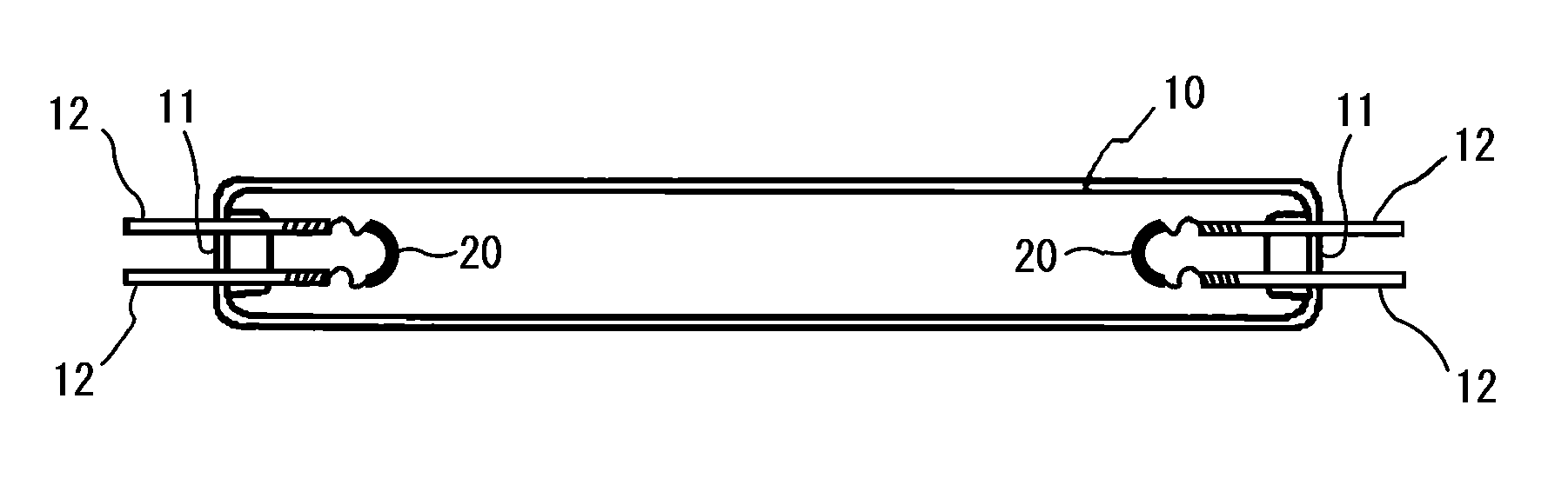
[0037]FIG. 1 shows the overall structure of an exemplary hot cathode fluorescent lamp. As shown in FIG. 1, the hot cathode fluorescent lamp can include: a glass tube 10, sealing parts 11 for sealing the glass tube 10 at its opposite ends; a pair of lead wires 12 that penetrate the sealing parts 11 from the inside toward the outside of the glass tube 10; and coil filaments 20 attached to the respective tip portions of the lead wires 12 inside the glass tube 10. The sealed glass tube 10 can contain mercury and a discharge gas. The coil filaments 20 can be coated with emitter in their fixed regions as described later.

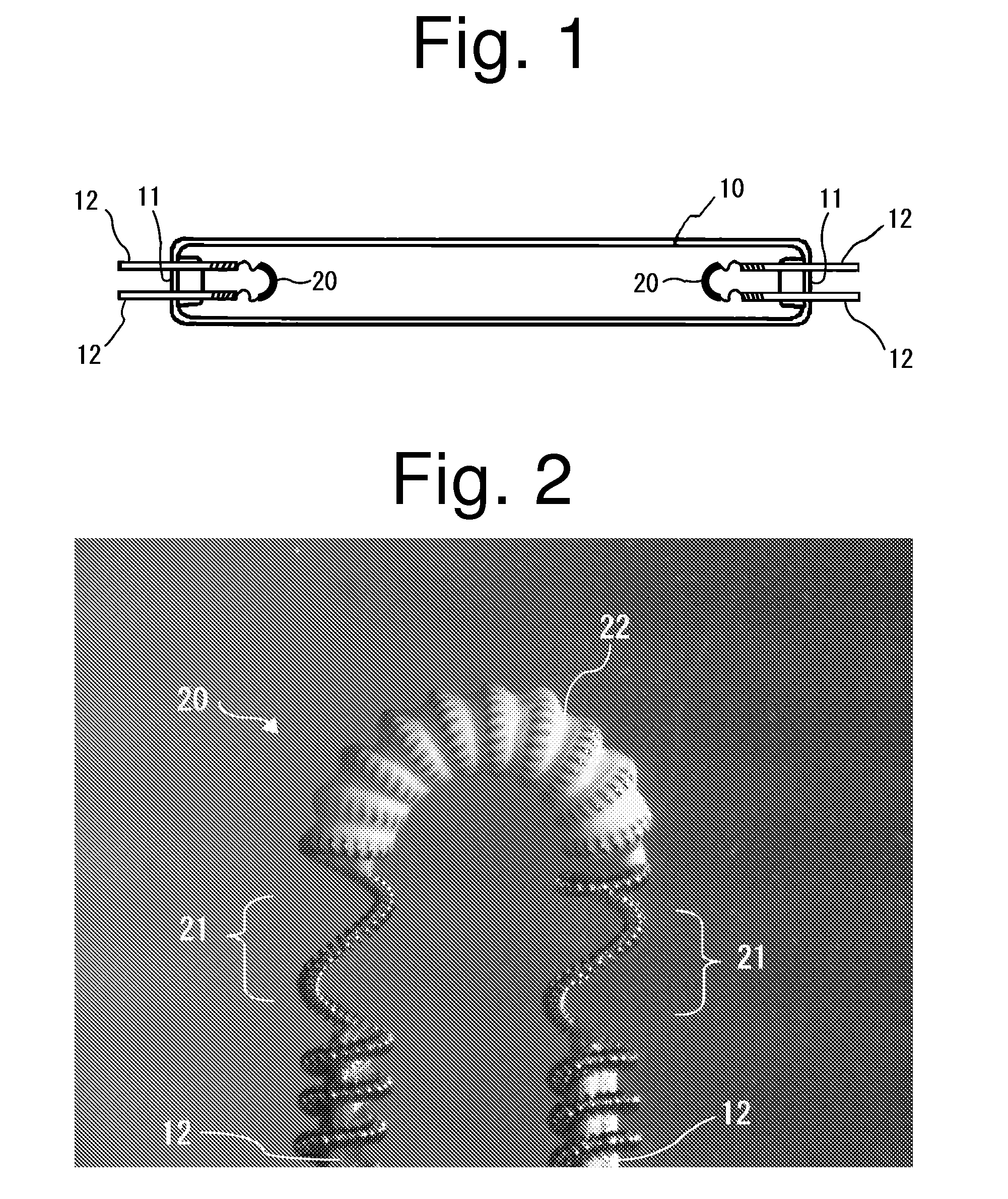
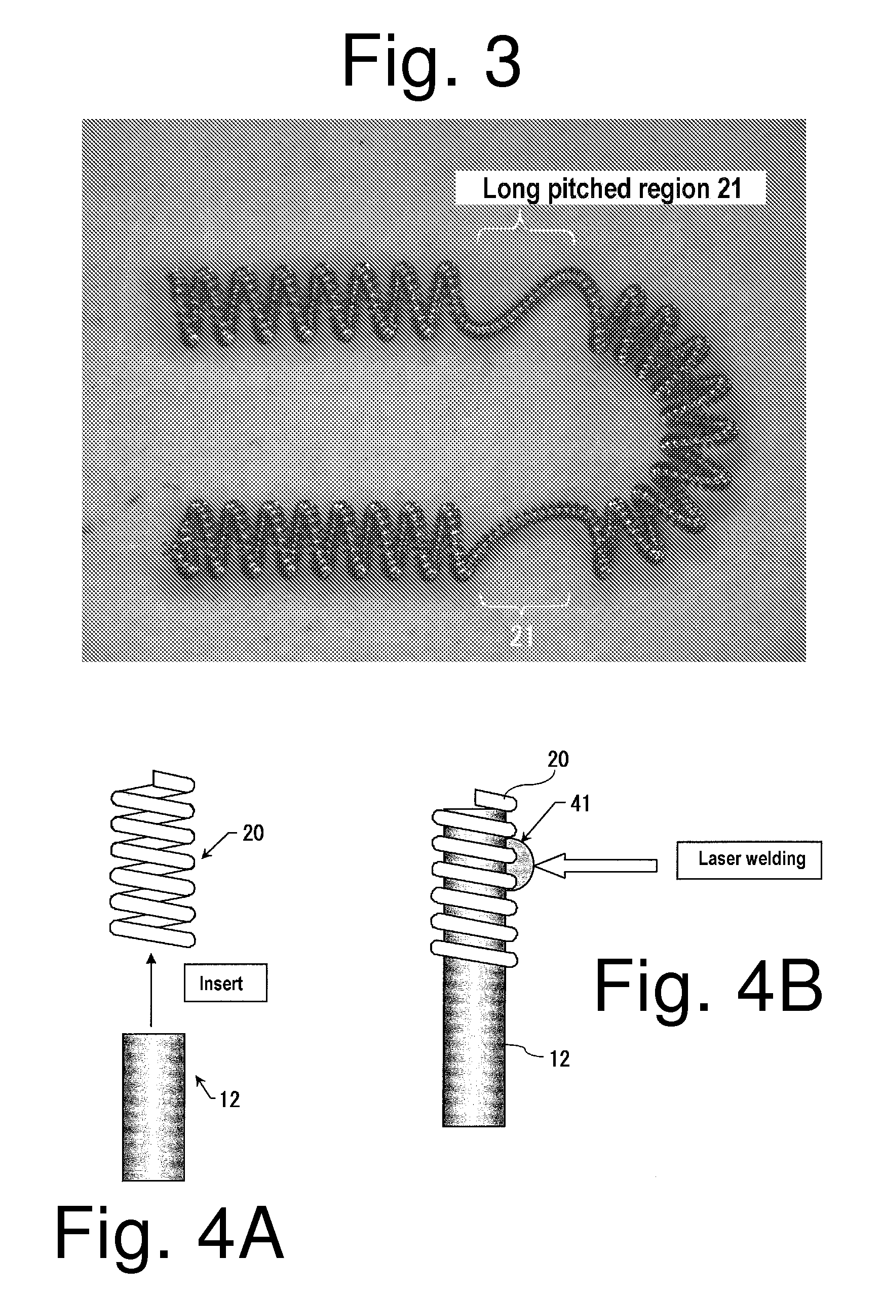
[0038]FIG. 2 is an enlarged photograph of the coil filament 20 fixed to the tip portions of the lead wires 12. FIG. 3 is an enlarged photograph of the overall structure of the coil filament 20 to which emitter ...


PUM


Abstract

A long-life hot cathode fluorescent lamp can include a pair of parallel lead wires that can be arranged at each end of a tube. A coiled filament can be connected at its opposite end portions to the lead wires. The coiled filament can have two long pitched regions in which a coil pitch is longer than regions outside of the long pitched regions. Emitter can be located in a region defined between the two long pitched regions. Shape characteristics and intensive current flow obtained by the presence of the long pitched regions can form the origins of discharge near the boundaries between long and short pitched regions. Accordingly, stable discharge can be achieved with the origins of discharge located at ends of the emitter. As a result, the hot cathode fluorescent lamp is allowed to have a long life and stable light emission characteristics.

Description

[0001]This application claims the priority benefit under 35 U.S.C. §119 of Japanese Patent Application No. 2009-071542 filed on Mar. 24, 2009, which is hereby incorporated in its entirety by reference.BACKGROUND[0002]1. Technical Field[0003]The presently disclosed subject matter relates to a long-life hot cathode fluorescent lamp with stable light emission characteristics.[0004]2. Related Art[0005]Cold cathode fluorescent lamps have widely been used as light sources of backlight units for use in large-sized liquid crystal televisions, for example. In light of the recent importance associated with energy savings, it has been suggested that hot cathode fluorescent lamps, superior in light emission efficiency to cold cathode fluorescent lamps, be used as light sources of backlight units.[0006]Light sources of backlight units for liquid crystal display devices have been required to be long life, and small in diameter. These two requirements should be satisfied when hot cathode fluoresce...

Claims


Application Information

Patent Timeline
IPC IPC(8): H01J63/04H01J1/16
CPCH01J61/0672
Inventor MATSUDA, JUNJIYOSHIDA, MITSUNARI
Owner STANLEY ELECTRIC CO LTD
Why Eureka
Try Eureka