
Lighting device and method of cooling lighting device

a lighting device and cooling technology, applied in the direction of lighting support devices, semiconductor devices for light sources, lighting and heating apparatus, etc., can solve the problems of many solid-state light emitters that do not operate well in high temperatures, and achieve the effects of improving efficiency, improving color output, and prolonging li

Active Publication Date: 2010-09-30
IDEAL IND LIGHTING LLC
View PDF54 Cites 37 Cited by
  • Summary
  • Abstract
  • Description
  • Claims
  • Application Information

AI Technical Summary

Benefits of technology

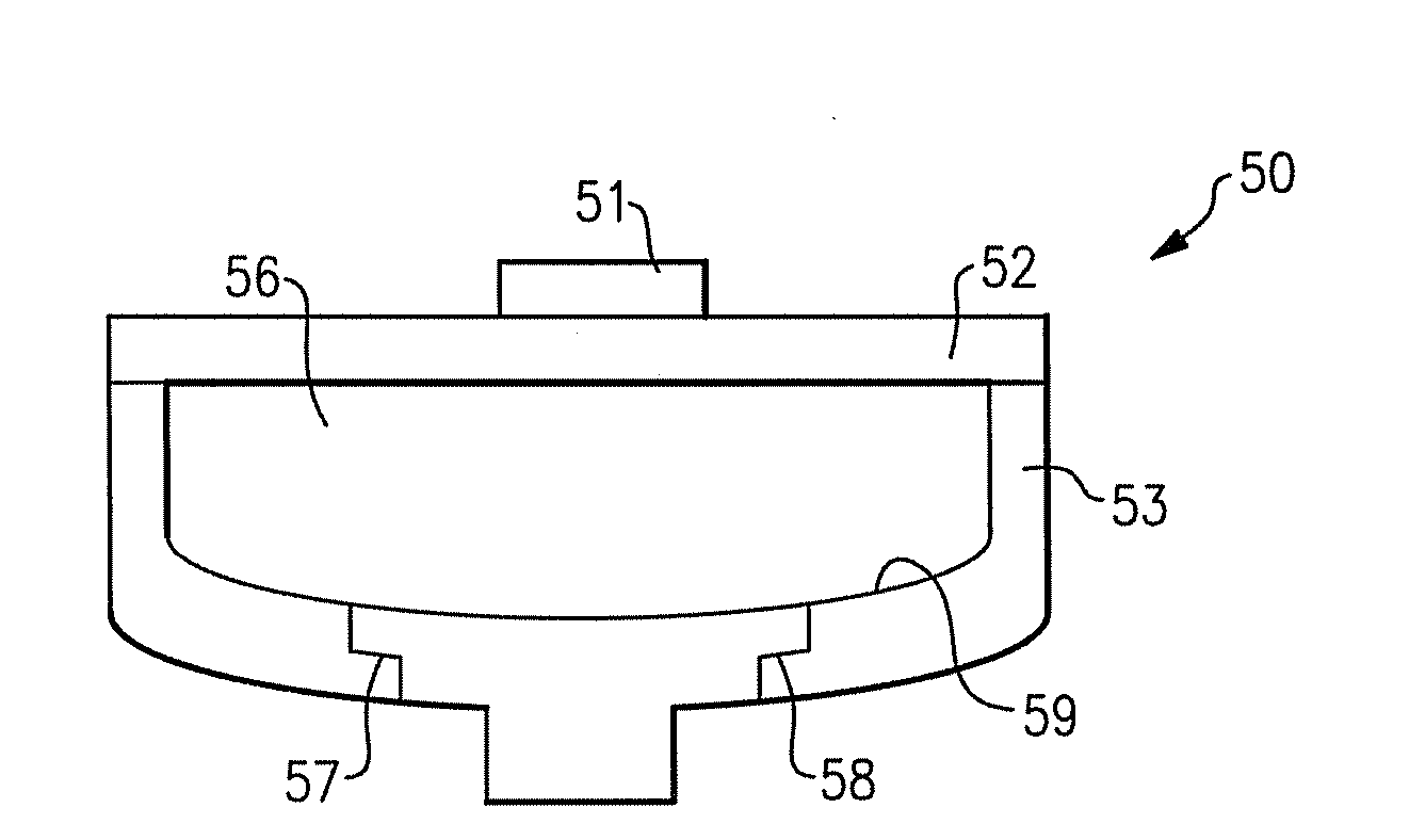
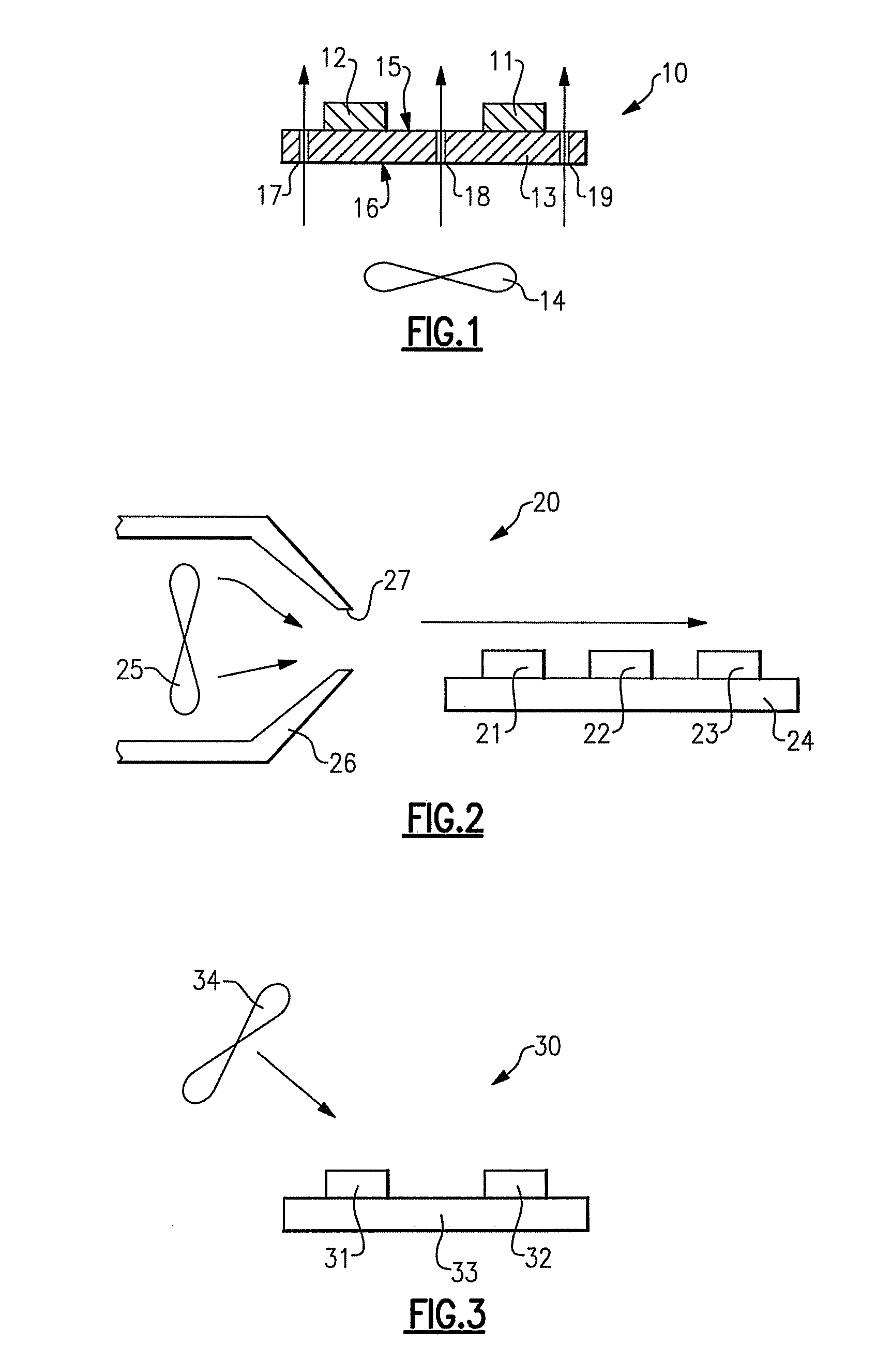
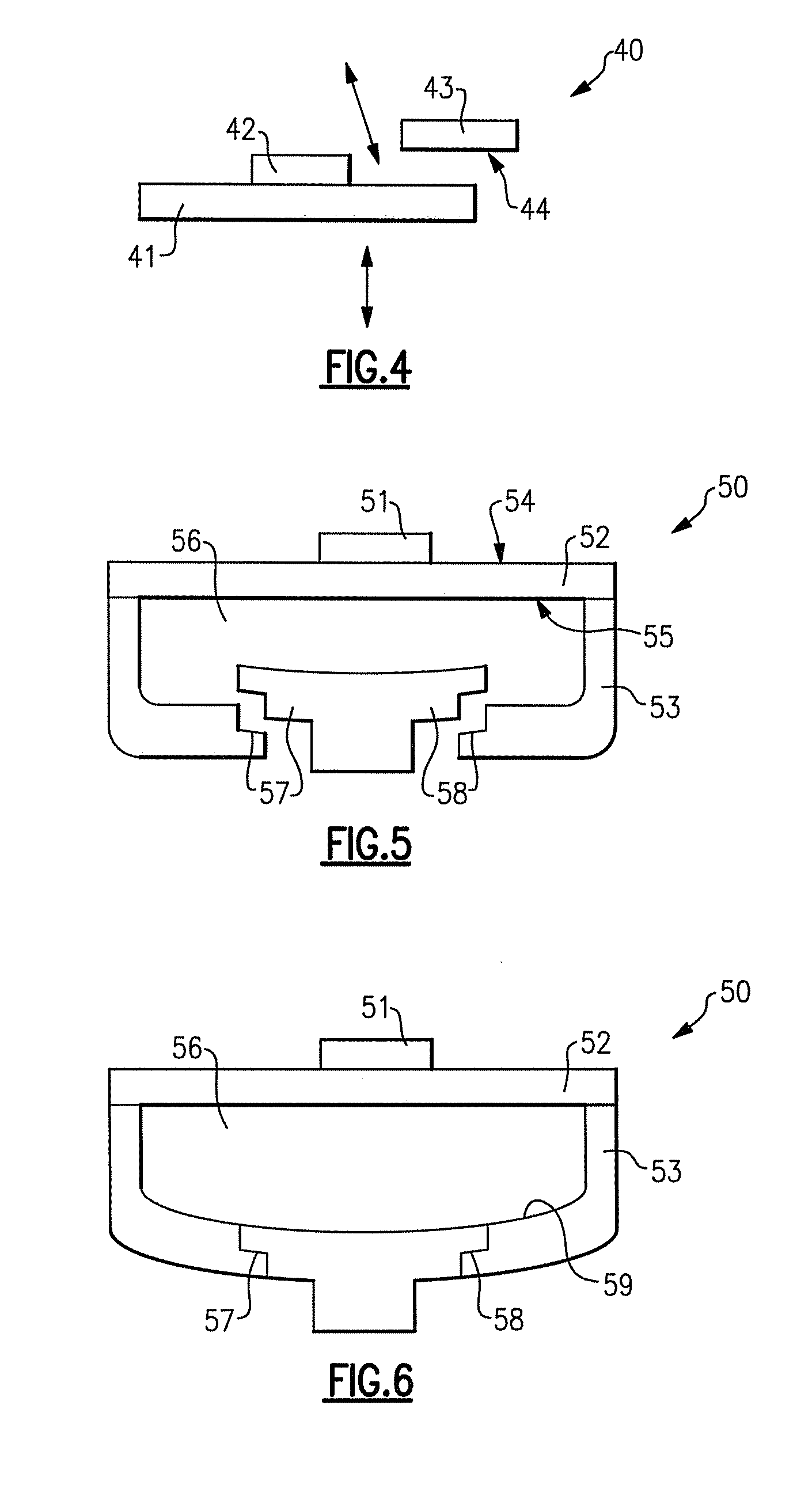
[0012]In order to provide longer life and / or greater efficiency and / or more consistent color output for lighting devices which include one or more solid state light emitters, e.g., one or more light emitting diodes, in accordance with the present inventive subject matter, there is provided a lighting device which comprises at least one solid state light emitter in which the junction temperature of the solid state light emitter(s) is managed (so as to be kept at or near the manufacturer's recommended junction temperature) by actively cooling the solid state light emitter(s) with fluid movement or fluid cooling that is in direct contact with the solid state light emitter(s) or in close proximity to the solid state light emitter(s).
[0013]In some embodiments of the present inventive subject matter, the temperature management provided makes it possible to reduce the size of or even eliminate altogether the use of a heat sink, which can be heavy, expensive, and / or potentially unsafe (since they are typically electrically conductive), and / or which can take up space, and / or which can have a negative impact on optical performance (e.g., due to taking up space and / or causing obscuration). Accordingly, such embodiments can provide reduction in weight, reduction in size and / or reduction in cost as a result of the ability (provided by the present inventive subject matter) to eliminate heat sinks and heat spreaders normally used to move the heat from solid state light emitters to ambient by increasing the effective surface area of the interface between the thermal source and ambient, thereby allowing more heat to be transported away from the light emitter to the environment and keeping the junction temperature low.
[0014]In order to minimize the thermal resistance and maximize the surface effect, heat sinks that are typically employed tend to have thick cross-sectional areas. The thermal conductivity is proportional to the cross-sectional area and inversely proportional to the distance the heat needs to be moved. Heat sinks are also made from materials that inherently have high thermal conductivities. Such materials include metals, metal alloys, ceramics, and polymers mixed with ceramic or metal or metalloid particles. One of the more common materials in aluminum. These heat sinks, in order to be effective, are often very large in comparison to the size of the solid state light emitters. Such heat sinks add large amounts of volume, weight and cost. One the objects of some aspects of the present inventive subject matter is to provide lighter, cheaper and smaller size lighting devices by removing (or reducing) the need for a heat sink or heat spreader by causing air to move directly over / around / adjacent to the lighting device to remove the heat directly from the lighting device.
[0015]In addition, cooling the solid state light emitter(s) directly makes it possible to cool the solid state light emitter(s) more rapidly since the heat capacity of the solid state light emitter(s) is usually very small relative to a large heat sink (i.e., the heat sink stores more heat in its large mass).
[0081]In some embodiments according to the seventh aspect of the present inventive subject matter, the solid state light emitter comprises at least one layer which substantially prevents liquid from passing therethrough.

Problems solved by technology

Many solid state light emitters, however, do not operate well in high temperatures.

Method used


Image

  • Lighting device and method of cooling lighting device
  • Lighting device and method of cooling lighting device
  • Lighting device and method of cooling lighting device

Examples


Embodiment Construction

[0092]The present inventive subject matter now will be described more fully hereinafter with reference to the accompanying drawings, in which embodiments of the inventive subject matter are shown. However, this inventive subject matter should not be construed as limited to the embodiments set forth herein. Rather, these embodiments are provided so that this disclosure will be thorough and complete, and will fully convey the scope of the inventive subject matter to those skilled in the art. Like numbers refer to like elements throughout. As used herein the term “and / or” includes any and all combinations of one or more of the associated listed items.

[0093]The terminology used herein is for the purpose of describing particular embodiments only and is not intended to be limiting of the inventive subject matter. As used herein, the singular forms “a”, “an” and “the” are intended to include the plural forms as well, unless the context clearly indicates otherwise. It will be further unders...


PUM


Abstract

A lighting device comprising a solid state light emitter and a fan, the fan blowing fluid toward the emitter. A lighting device comprising a solid state light emitter and a baffle, the solid state light emitter being movable. A lighting device comprising a solid state light emitter, a substrate and a diaphragm, the diaphragm defining a chamber having a valve and being movable. A lighting device comprising a housing and a solid state light emitter within the housing, the solid state light emitter being movable. Also, methods of cooling a lighting device.

Description

FIELD OF THE INVENTIVE SUBJECT MATTER[0001]The present inventive subject matter is directed to lighting devices and methods of cooling lighting devices. In some aspects, the present inventive subject matter is directed more particularly to a lighting device which comprises one or more solid state light emitters and one or more elements for cooling the solid state light emitter(s). In some aspects, the present inventive subject matter is directed more particularly to a method of cooling one or more solid state light emitters in a lighting device.BACKGROUND[0002]A large proportion (some estimates are as high as twenty-five percent) of the electricity generated in the United States each year goes to lighting. Accordingly, there is an ongoing need to provide lighting which is more energy-efficient. It is well known that incandescent light bulbs are very energy-inefficient light sources—about ninety percent of the electricity they consume is released as heat rather than light. Fluorescen...

Claims


Application Information

Patent Timeline
Patent Type & Authority Applications(United States)
IPC IPC(8): F21V21/00F21V29/00
CPCF21S48/325F21Y2101/02F21V29/677F21V29/248F21V29/58F21V29/027F21S45/50F21Y2115/10F21S45/43F21S45/46F21Y2101/00
Inventor VAN DE VEN, ANTONY PAUL
Owner IDEAL IND LIGHTING LLC
Learn More