
Industrial controller employing the network ring topology

a network ring and controller technology, applied in the field of industrial controllers, can solve the problems of relatively long time to reconnect the network, and the error detection time of such ring systems can be quite fast, and achieve the effect of faster recovery tim

Active Publication Date: 2010-09-30
ROCKWELL AUTOMATION TECH
View PDF9 Cites 28 Cited by
  • Summary
  • Abstract
  • Description
  • Claims
  • Application Information

AI Technical Summary

Benefits of technology

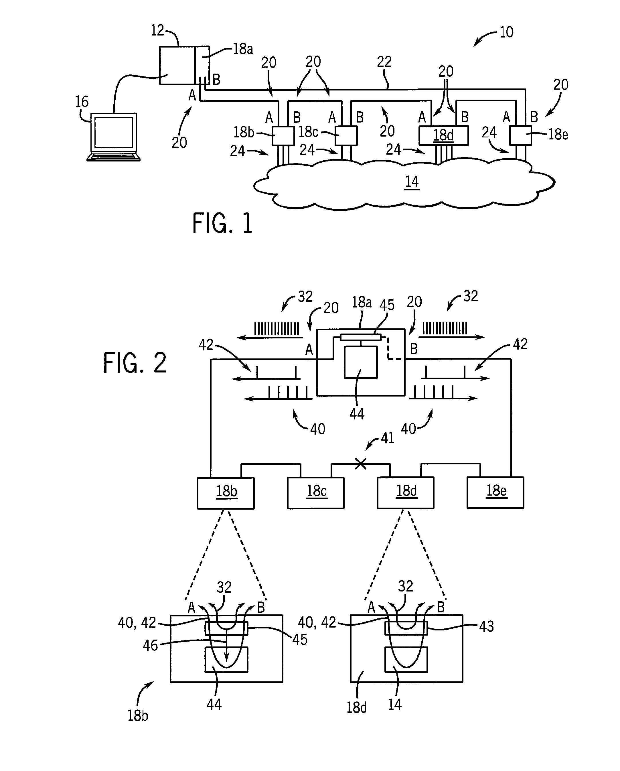
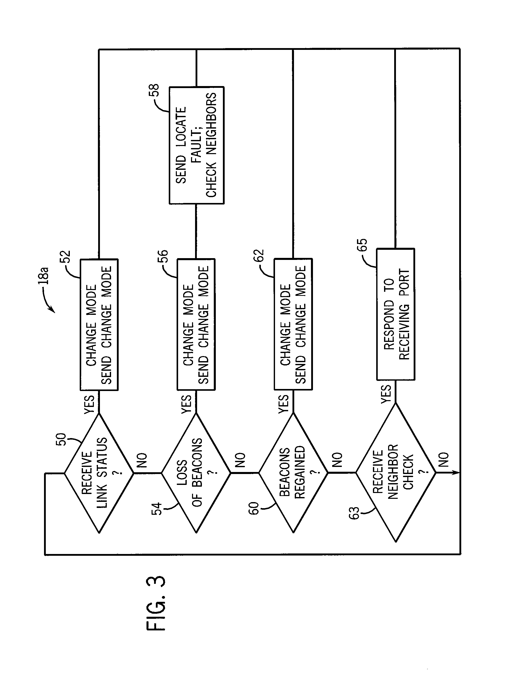
[0006]The present inventors have recognized that even faster recovery time can be achieved by communicating the topology change in the beacon frame itself, along with monitoring reception or non-reception of beacon frames in ring nodes. Such an approach practically requires a hardware processing of the beacon frames at the network nodes with custom embedded switches in the form of application specific integrated circuits (ASIC), so that the network nodes can monitor reception or non-reception of the beacon frame along with data in the beacon frame rather than simply passing the beacons from port to port as is required in prior art systems.
[0007]The benefit is much faster recovery times; however, such hardware processing would ordinarily preclude use of this system with nodes using commercially available switching integrated circuits (IC). Accordingly, the present invention also contemplates a dual-mode announcing system that transmits topology state change both in the beacon frames and in special announce frames that can be processed by ring protocol aware nodes using commercial switching IC. In addition, the present invention also allows ring protocol unaware commercial off-the-shelf managed switches to be directly connected to ring when the switches are appropriately configured.

Problems solved by technology

These protocols can take a relatively long time to reconnect the network (as much as 30 seconds) and thus are unacceptable for industrial control networks where the controlled process cannot be undirected during this period without disastrous consequences.
The error detection time of such ring systems can be quite fast, limited principally by the transmission rate of the beacons (every several milliseconds).

Method used


Image

  • Industrial controller employing the network ring topology
  • Industrial controller employing the network ring topology
  • Industrial controller employing the network ring topology

Examples


Embodiment Construction

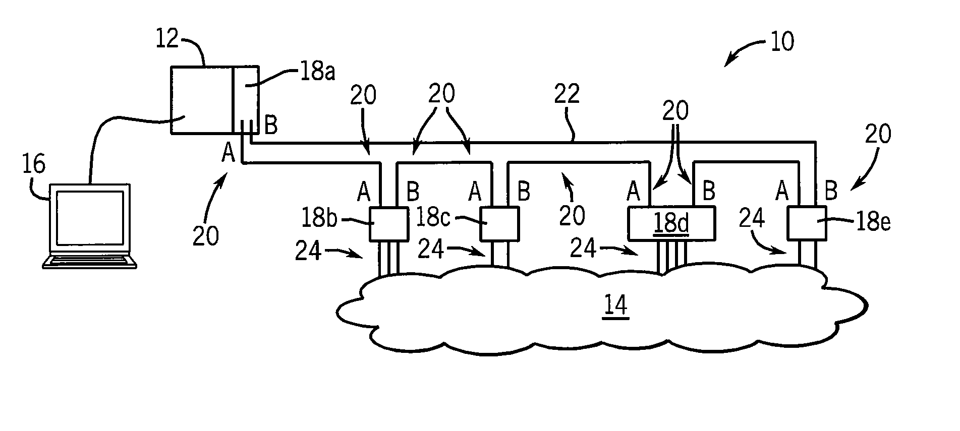
[0015]Referring now to FIG. 1, an industrial control network 10 may include, for example, a programmable logic controller 12 executing a stored program to provide for real-time control of an industrial process 14. Real-time control, in this context, means control that is subject to well-defined maximum delay periods between an output signal generated by the programmable logic controller 12 and electrical signal sent to an actuator in the industrial process 14, and similarly well-defined maximum delay period between the generation of a signal by a sensor in the industrial process 14 and its receipt and processing by the programmable logic controller 12.

[0016]Normally the programmable logic controller 12 includes an electronic computer executing a stored program providing detailed logic for the necessary control. Often the stored program is generated uniquely for the particular industrial process 14.

[0017]The programmable logic controller 12 may communicate with a terminal device 16 t...


PUM


Abstract

A network for an industrial control system employs a ring topology that is normally opened by a ring supervisor at the ring supervisor. Upon failure of the network, the ring supervisor reconnects the ring to provide an alternative transmission path around the failure point. High speed operation is reconciled with the ability to use commercial switching integrated circuits through a dual communication channel of communicating a network state as either closed or open using both high-speed hardware handled beacon frames and low-speed software processed announce frames.

Description

BACKGROUND OF THE INVENTION[0001]The subject matter as disclosed herein relates to industrial controllers communicating among components by computer networks and in particular by Ethernet type networks.[0002]Networks used for communication among industrial controllers differ from standard networks in that they must operate to communicate data reliably within predefined time limits. Often this is accomplished by additional communication protocols that reserve network bandwidth and schedule messages to prevent collisions and the like that can introduce unpredictable delay into network communications.[0003]Many computer networks also incorporate protocols to repair the network in the event of network node failure. These protocols can take a relatively long time to reconnect the network (as much as 30 seconds) and thus are unacceptable for industrial control networks where the controlled process cannot be undirected during this period without disastrous consequences.[0004]The risk of de...

Claims


Application Information

Patent Timeline
Patent Type & Authority Applications(United States)
IPC IPC(8): G06F11/00
CPCG05B19/0423H04L41/0226H04L41/0806H04L69/18H04L67/34H04L69/08H04L41/0856
Inventor BALASUMBRAMANIAN, SIVARAMMOLDOVANSKY, ANATOLYBATKE, BRIAN A.
Owner ROCKWELL AUTOMATION TECH
Learn More