Method for driving smart antennas in a communication network

a communication network and smart antenna technology, applied in the direction of frequency-division multiplex, instruments, synchronisation arrangement, etc., can solve the problems of expensive, static and expensive, antenna aiming is a costly and not very fast procedure, and the signal strength and bandwidth establish an upper limit at the capacity of a communication link

Inactive Publication Date: 2010-09-30
THALES SA
View PDF26 Cites 32 Cited by
  • Summary
  • Abstract
  • Description
  • Claims
  • Application Information

AI Technical Summary

Problems solved by technology

However, in his theory of information, Shannon shows that the radiofrequency RF signal strength and bandwidth establish an upper limit at the capacity of a communication link:
This approach is tedious, static and costly.
Even when motorized, the aiming of the antennas is a costly and not very fast procedure.
However, any relaying notably involves:either a loss of bandwidth and an increase in latency (single-radio mode),or maintained bandwidth and latency at the cost of two radios (and not just one).
MIMO is not effective in LOS mode (becaus

Method used


Image

  • Method for driving smart antennas in a communication network
  • Method for driving smart antennas in a communication network
  • Method for driving smart antennas in a communication network

Examples


example a

Received Power Optimization Criterion

[0123]The power criterion is the simplest to use (measuring the RSSI, standing for Received Signal Strength Indication). It is indirectly linked to the robustness of the communication.

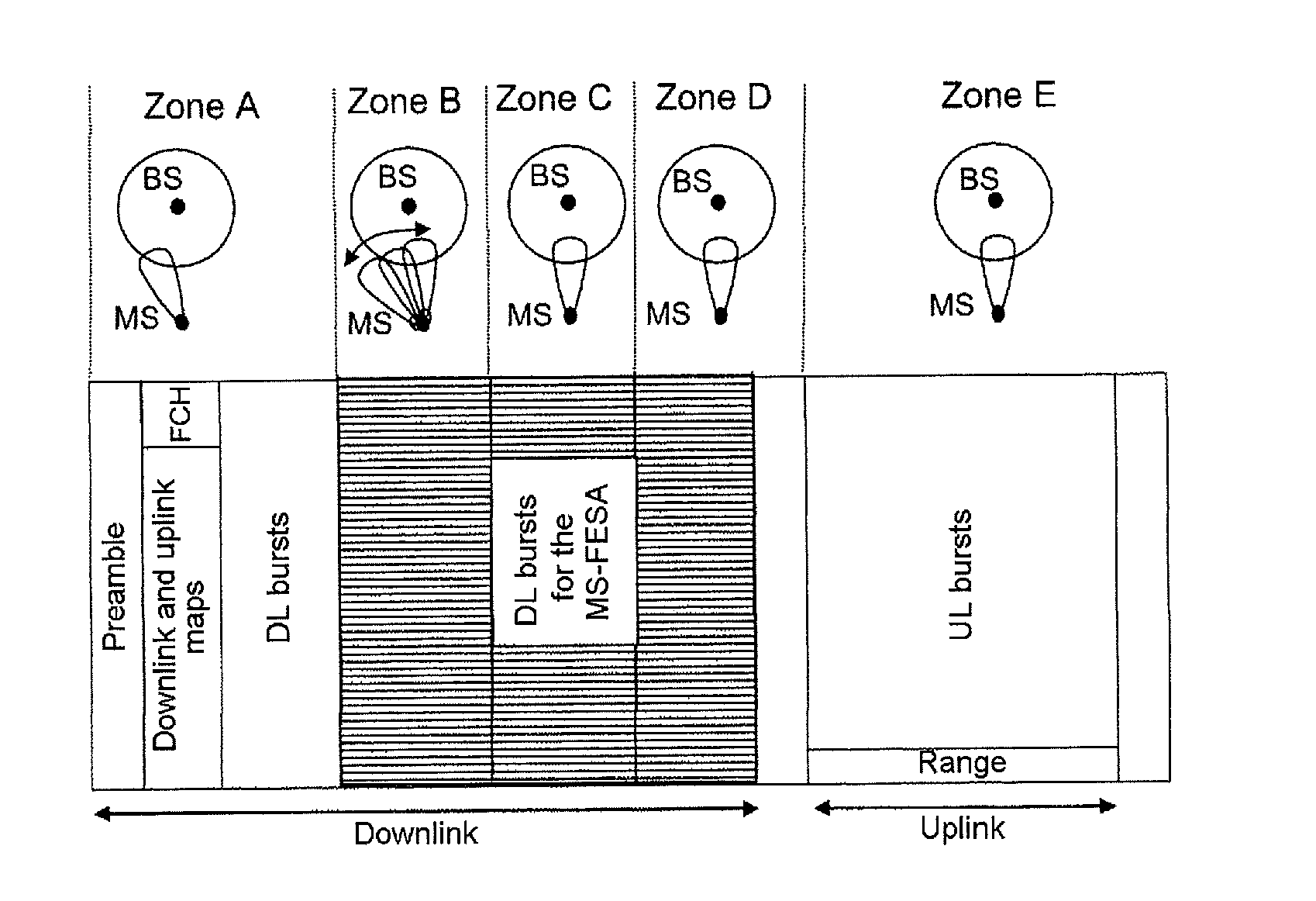
[0124]The mobile station MS exploits times in the downlink subframe in which no burst is intended for it, that is to say that it receives no dedicated information from the base station, to measure the received signal strengths on the other directions of the beam from its FESA antenna. In practical terms, for several beam aiming angle values, it determines a received signal strength or energy, then it can calculate the average of all the signal strength values.

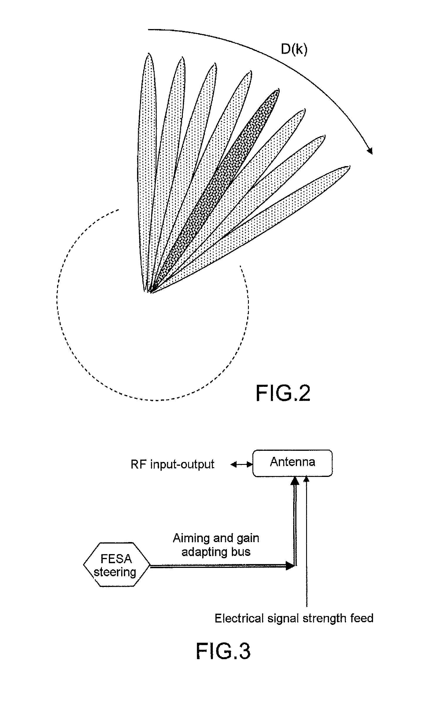
[0125]The calculations are, for example, carried out in the antenna aiming device situated in the upper Mac layer.

[0126]These measurements are valid in as much as the base station BS is transmitting at the measured instants, that is to say that the BS is interested in the other MSs. It delivers their respective...

example b

Combination of Signal Strength and Signal / Noise Ratio or SNR

[0131]The SNR value is an excellent criterion because it is directly linked to the demodulation capability. However, it assumes that the mobile station MS demodulates symbols. This therefore means that the WiMAX MS is modified to also demodulate symbols that are not intended for it, and do so in order to determine the SNR therefrom. The symbols acquired by the mobile station are decoded in order to retrieve the modulated data then determine the value of the signal-to-noise ratio by executing statistical methods known to those skilled in the art. This method can be longer than the previous one because it entails waiting for the duration of a symbol. This method can be coupled with the use of the channel coding statistics.

[0132]The algorithm-based procedure implemented can be as follows, by considering the aiming of the FESA antenna on the MS obtained on the preceding frame and the omnidirectional pattern on the antenna of th...


PUM


Abstract

A method and device for implementing a smart antenna in a network that uses a deterministic access protocol, one or more mobile stations MS and at least one base station BS, the transmitted data being included in a data frame, wherein it comprises at least the following steps: On entry into the network:
    • the step of synchronizing a mobile station MS equipped with an FESA directional antenna on a transmission from the base station by changing beam for a duration at least equal to a frame in order to aim the directional beam toward the base station BS to obtain the best signal reception,
    • the step of following the synchronization of the mobile station on the transmission from the base station, and implementing an aiming tracking algorithm in order to retain the best signal reception,
    • the step of determining the parameters for defining the downlink or the uplink by decoding signaling messages contained in the message transmitted by the base station,
    • triggering a network entry procedure.
Once the mobile station MS has entered the network:
  • the selection of the new beam being based on a mechanism with hysteresis that uses a linear filtering preceded by a hop-based rejection step or that directly uses a nonlinear filter.
  • Description

    FIELD OF THE INVENTION[0001]The invention relates notably to the steering of smart antennas, hereinafter called FESA or Fast Electronically Steerable Antennas. These so-called smart antennas are characterized by a highly directional lobe which can be oriented in a given direction in a very short time (a few hundred nanoseconds). They are used, for example, in vehicle, boat and aircraft-type mobiles for which the implementation of directional lobe antennas with dynamic aiming is vitally important.[0002]The implementation of such antennas for fixed points can also represent an advantage, in order to do away with manual aiming for example.[0003]The present invention also relates to a method that makes it possible to use the smart antennas in a wireless communication system.BACKGROUND OF THE INVENTION[0004]In recent years, significant progress has been made in the field of antennas in order to improve the link budget and their range. The prior art describes various techniques with which...

    Claims


    Application Information

    Patent Timeline
    IPC IPC(8): H04B7/14H04W56/00
    CPCG01S19/39H04W72/046H04W16/28G01S19/393
    Inventor HETHUIN, SERGEDUPREZ, ADRIEN
    Owner THALES SA
    Why Eureka
    Try Eureka