Polyurethane/bone compositions and methods

a polyurethane and bone technology, applied in the field of polyurethane/bone compositions and methods, can solve the problems of inability to present osteoconductive, load bearing and resorbable injection technology, and achieve the effect of less invasive application

Inactive Publication Date: 2010-09-30
VANDERBILT UNIV
View PDF8 Cites 6 Cited by
  • Summary
  • Abstract
  • Description
  • Claims
  • Application Information

AI Technical Summary

Benefits of technology

[0006]Preferably the composite material is flowable. Thus, the material m

Problems solved by technology

However, an injectable technology that is osteoconductive, lo

Method used


Image

  • Polyurethane/bone compositions and methods
  • Polyurethane/bone compositions and methods

Examples


examples

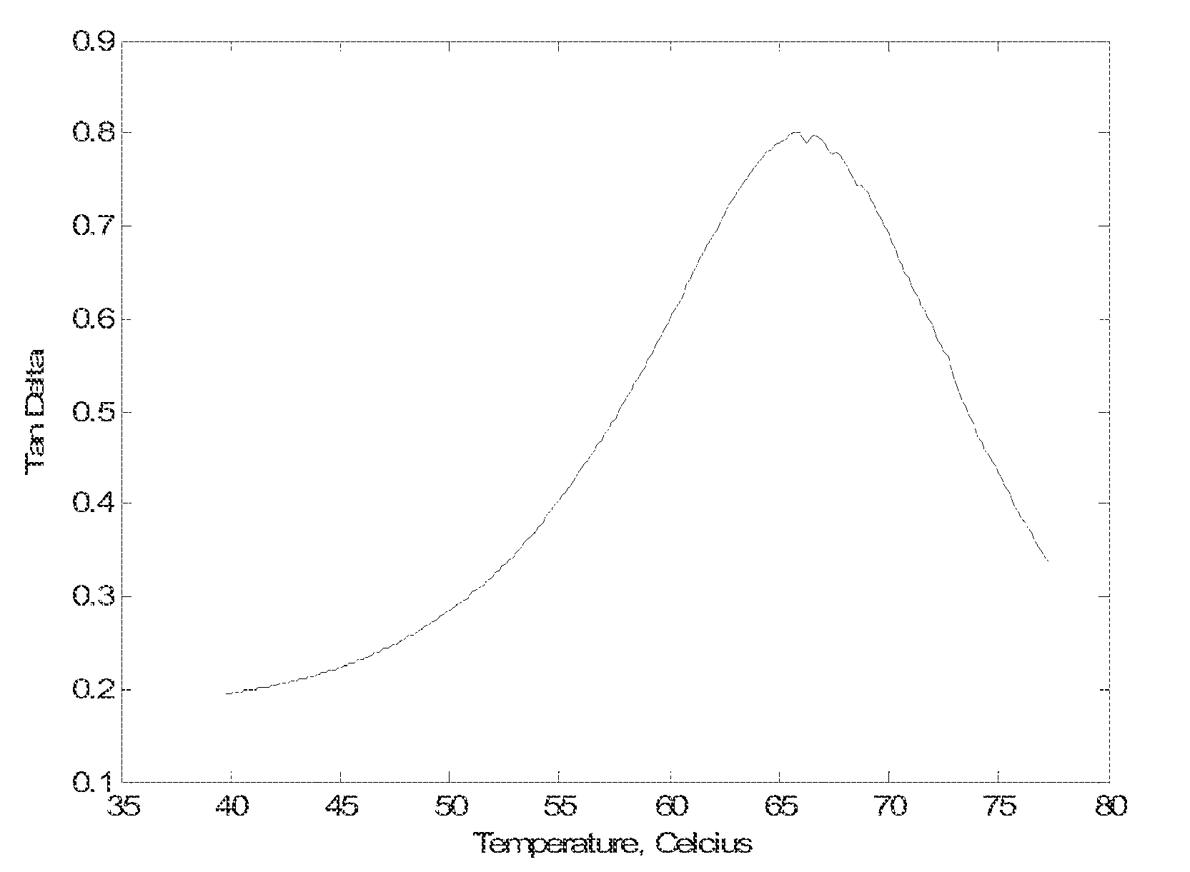
[0030]Materials and Methods. Bone / poly(ester urethane) (PEUR) composites are composed of lysine diisocyanate (LDI), polycaprolactone (molecular weight 300) (PCL 300), and mineralized bone powder (100-500 microns) (MBP). Coscat 83, an organobismuth catalyst, and Tegoamin 33, an amine catalyst, were both studied as potential catalysts. Polymers synthesized from LDI and polyester polyols have been reported to support cell attachment and biodegrade to non-cytotoxic degradation products. Surface activated bone, etched using an adapted procedure from Osteotech, Inc, was interchanged with the unmodified MBP. During the polyurethane reaction temperature was monitored using a temperature probe to monitor the heat of reaction. Samples were cast as 11 mm×11 mm cylinders for compression testing, which was conducted on a MTS with a 13 kN load cell. Dynamic mechanical properties were measured by dynamic mechanical analysis (DMA) in 3-point bending mode. FT-IR was performed to ensure that there wa...


PUM

PropertyMeasurementUnit
Pressureaaaaaaaaaa
Pressureaaaaaaaaaa
Lengthaaaaaaaaaa

Abstract

A flowable, injectable composite that comprises mineralized allograft bone; and at least one degradable polyurethane that has a quasi-prepolymer and a resin mix, the resin mix having a polyester polyol and a catalyst; wherein the composite has a compression strength of greater than about 10 MPa and a modulus of greater than about 1 GPa.

Description

PRIORITY INFORMATION[0001]This application claims benefit to U.S. Patent Application No. 60 / 970,205, the contents of which are incorporated herein by reference in their entirety.GOVERNMENT SUPPORT[0002]This invention was made with support from Department of Defense grant number DOD-2110-PO5-694362. The United States Government has rights to this invention.BACKGROUND OF THE INVENTION[0003]The need for orthopedic care to address vertebral fractures / defects is becoming an increasing demand due to the growing elderly population in the U.S. Like most surgical procedures, vertebral surgeries can require extensive post-operative care. In order to reduce the recovery time, several minimum invasive surgical techniques have been developed to repair such defects. However, an injectable technology that is osteoconductive, load bearing and resorbable currently does not currently exist.SUMMARY OF THE INVENTION[0004]Aspects of the present invention relate to weight-bearing composites of mineralize...

Claims


Application Information

Patent Timeline
IPC IPC(8): A61K35/32A61F2/28
CPCA61F2/2846A61F2002/2817A61L27/3608A61L27/48C08L75/04
Inventor GUELCHER, SCOTT A.DUMAS, JERALD
Owner VANDERBILT UNIV
Why Eureka
Try Eureka