Heat transport device, electronic apparatus, and heat transport manufacturing method

a heat transport device and heat transport manufacturing technology, applied in semiconductor devices, cooling/ventilation/heating modifications, heating elements, etc., can solve the problems of heat transport device working fluid not flowing properly, heat transport is not performed properly, friction resistance and pressure loss are large, etc., to achieve convenient manufacturing, efficient heat transport, and high reliability

Inactive Publication Date: 2010-10-07
SONY CORP
View PDF9 Cites 25 Cited by
  • Summary
  • Abstract
  • Description
  • Claims
  • Application Information

AI Technical Summary

Benefits of technology

[0007]In view of the above-mentioned circumstances, it is desirable to provide a heat transport device realizing higher heat transport efficiency, and an electronic apparatus including the heat transport device. It is further desirable to provide a heat transport device manufacturing method that realizes easier manufacture with higher reliability.
[0023]According to the heat transport device of the embodiments of the present invention, higher heat transport efficiency is realized. According to the heat transport device manufacturing method of the embodiment of the present invention, easier manufacture and higher reliability are realized.

Problems solved by technology

However, because carbon nanotube has a nanostructure, compared to a case where a flow path or the like for a working fluid is made of a metal plate or the like having a flat surface, a friction resistance and a pressure loss are large.
Then, there is a fear that the working fluid does not flow in a heat transport device properly, and as a result, heat transport is not performed properly.

Method used


Image

  • Heat transport device, electronic apparatus, and heat transport manufacturing method
  • Heat transport device, electronic apparatus, and heat transport manufacturing method
  • Heat transport device, electronic apparatus, and heat transport manufacturing method

Examples


first embodiment

[0045](Structure of Heat Spreader 1)

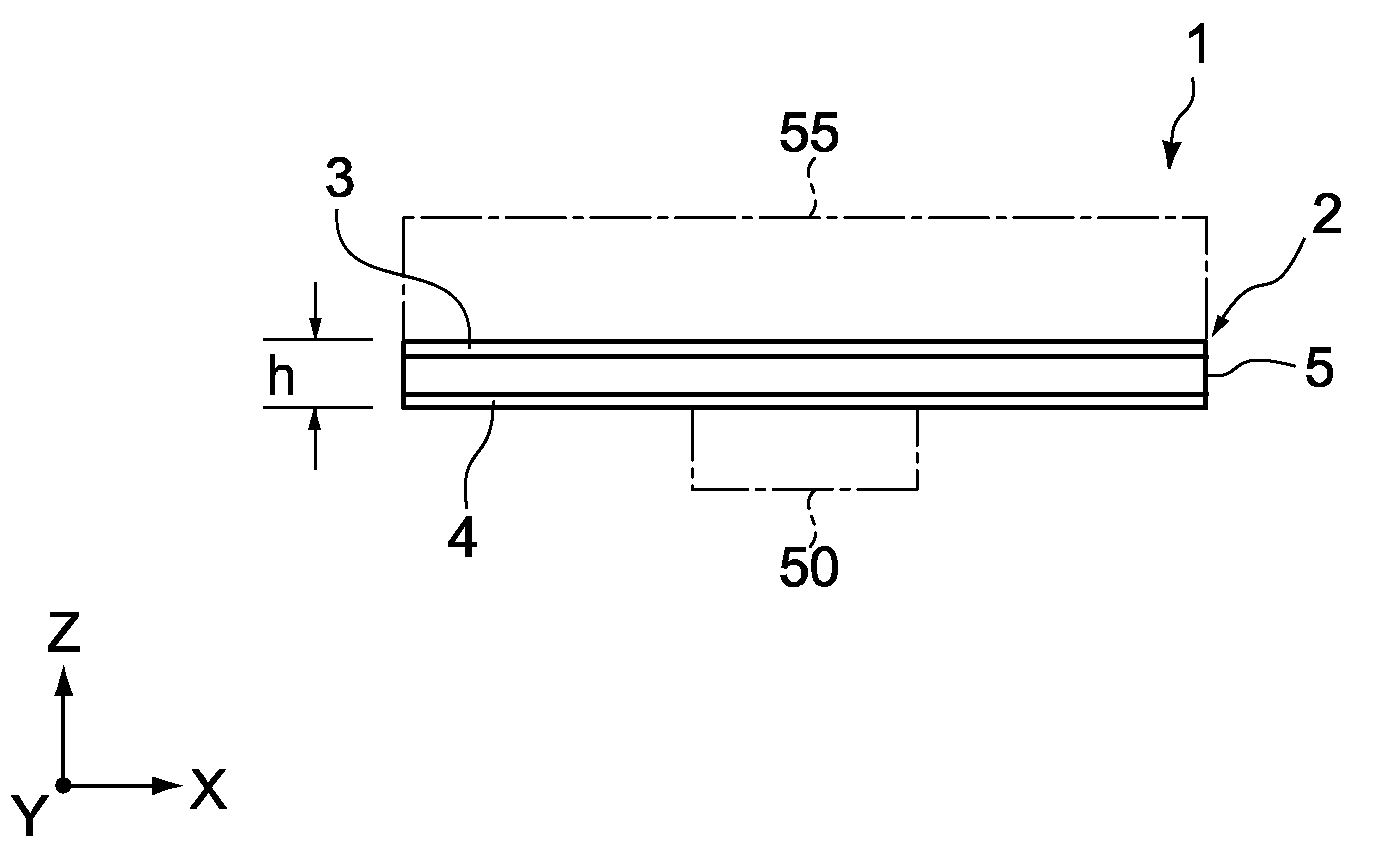
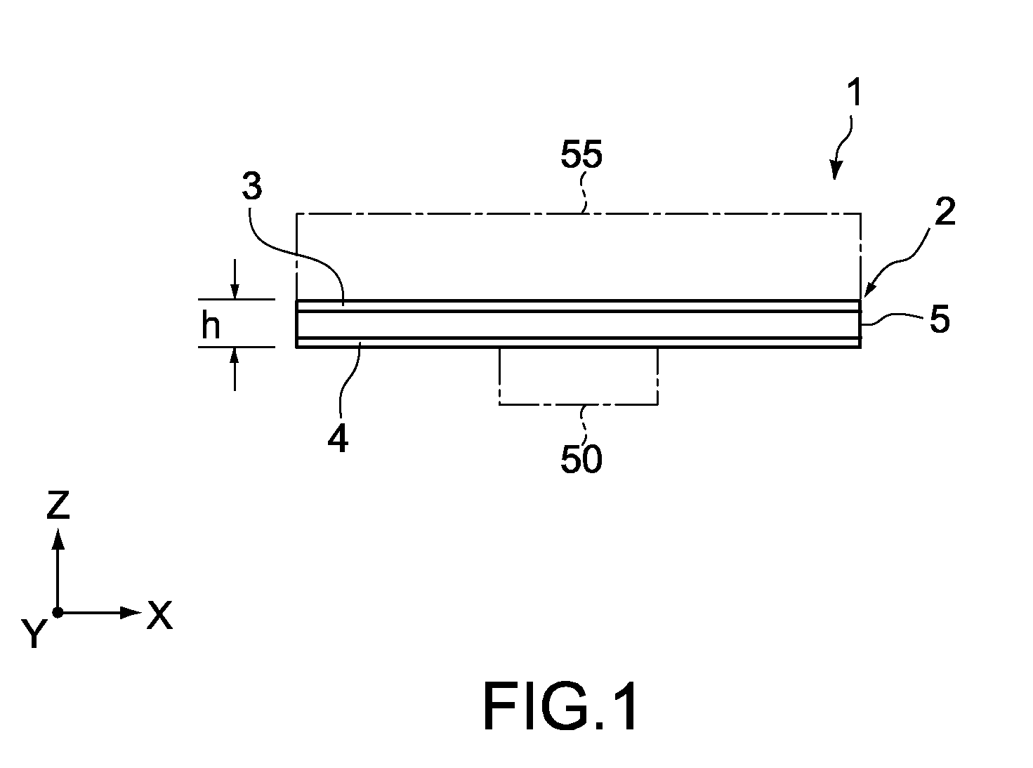
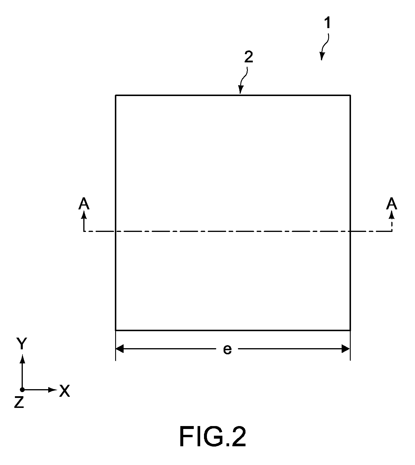
[0046]FIG. 1 is a side view showing a heat spreader 1 of a first embodiment of the present invention, the heat spreader being thermally connected to a heat source. FIG. 2 is a plan view showing the heat spreader 1 of FIG. 1.

[0047]As shown in FIGS. 1-2, the heat spreader 1 includes a container 2. The container 2 includes a heat reception plate 4 (first base member), a heat radiation plate 3, and sidewalls 5. The heat radiation plate 3 is provided so as to face the heat reception plate 4. The sidewalls 5 tightly bond the heat reception plate 4 and the heat radiation plate 3.

[0048]The heat radiation plate 3, the heat reception plate 4, and the sidewalls 5 may be bonded by brazing, that is, welded, or may be bonded with an adhesive material depending on the materials. The heat radiation plate 3, the heat reception plate 4, and the sidewalls 5 are made of a metal material, for example. The metal material is for example, copper having a high thermal con...

second embodiment

Structure of Heat Spreader 11

[0105]FIG. 11 is a sectional view showing a heat spreader 11 according to a second embodiment of the present invention.

[0106]Hereinafter, components, functions, and the like similar to those of the heat spreader 1 of the first embodiment will be attached with similar reference symbols, the description will be simplified or omitted, and different part will mainly be described.

[0107]The heat spreader 11 includes a container 12. The container 12 includes a heat reception plate 14, a heat radiation plate 13, and sidewalls 15. The heat radiation plate 13 is provided so as to face the heat reception plate 14. The sidewalls 15 tightly bond the heat reception plate 14 and the heat radiation plate 13. The container 12 further includes a refrigerant sealed therein. An inner space of the container 12 mainly serves as a flow path 16 for the refrigerant.

[0108]The heat reception plate 14 includes a heat reception surface 141, an evaporation surface 142, and a bond are...

third embodiment

Structure of Heat Spreader 21

[0124]FIG. 14 is an exploded perspective view of a heat spreader 21 according to a third embodiment of the present invention.

[0125]The heat spreader 21 includes a container 22. The container 22 includes a heat reception plate 24, a heat radiation plate 23, and bond areas 281 of a plurality of flow path plate members 28. The heat radiation plate 23 is provided so as to face the heat reception plate 24. The container 22 further includes a refrigerant sealed therein.

[0126]The heat reception plate 24 has a structure same as the structure of the heat reception plate 4. The heat reception plate 24 includes a heat reception surface 241, an evaporation surface 242, and a bond area 243.

[0127]The bond area 243 is bonded to the bond areas 281 of the plurality of flow path plate members 28.

[0128]An evaporation portion 27 having a structure same as the evaporation portion 7 is provided on the evaporation surface 242.

[0129]A heat source is thermally connected to the h...


PUM


Abstract

A heat transport device includes a working fluid, an evaporation portion, a condenser portion, a flow path portion, a concave portion, and a protrusion portion. The evaporation portion causes the working fluid to evaporate from a liquid phase to a vapor phase. The condenser portion communicates with the evaporation portion, and causes the working fluid to condense from the vapor phase to the liquid phase. The flow path portion causes the working fluid condensed in the condenser portion to the liquid phase to flow to the evaporation portion. The concave portion is provided on at least one of the evaporation portion and the flow path portion, in which the liquid-phase working fluid flows. The protrusion portion is made of nanomaterial protruding from an inner wall side surface of the concave portion such that the protrusion portion partially covers an opening surface of the concave portion.

Description

BACKGROUND OF THE INVENTION[0001]1. Field of the Invention[0002]The present invention relates to a heat transport device thermally connected to a heat source of an electronic apparatus, an electronic apparatus including the heat transport device, and a heat transport device manufacturing method.[0003]2. Description of the Related Art[0004]A heat transport device such as a heat spreader, a heat pipe, or a CPL (Capillary Pumped Loop) has been used as a device thermally connected to a heat source of an electronic apparatus, such as a CPU (Central Processing Unit) of a PC (Personal Computer), to absorb and diffuse heat of the heat source. For example, a solid-type metal heat transport device made of for example a copper plate is known, and a heat transport device including a working fluid has been proposed recently.[0005]It is known that nanomaterials such as carbon nanotube are high in thermal conductivity and contribute to acceleration of evaporation. As a heat transport device using ...

Claims


Application Information

Patent Timeline
Patent Type & Authority Applications(United States)
IPC IPC(8): F28D15/00
CPCF28D15/046H01L23/427H05K7/20481H05K7/2029H01L2924/0002H01L2924/00
Inventor HASHIMOTO, MITSUOYAZAWA, KAZUAKIKASAI, HIROTOISHIDA, YUICHIRYOSON, HIROYUKI
Owner SONY CORP
Why Eureka
Try Eureka