Power tool with brushless motor

Inactive Publication Date: 2010-10-07
MAX CO LTD
View PDF4 Cites 64 Cited by
  • Summary
  • Abstract
  • Description
  • Claims
  • Application Information

AI Technical Summary

Benefits of technology

[0009]According to one or more embodiments of the invention, there is provided a power tool with a brushless motor which, by making efficient use of a dead space provided due to the structural characteristic of the power tool, without increasing the size of the wh

Problems solved by technology

Thus, when the driving of the motor is kept ON, the electronic parts are overheated and broken, thereby causing a functional damage of the motor such as the breakdown of the motor and the reduced efficiency of the output thereof, with the result that an operation of the power tool is hindered and thus a reliability of the power tool is impaired.
At the construction site, the power tool is used even under the floor, on the attic and the like which are narrow and hard to operate the power tool.
Therefore, the provision of the

Method used


Image

  • Power tool with brushless motor
  • Power tool with brushless motor
  • Power tool with brushless motor

Examples


first exemplary embodiment

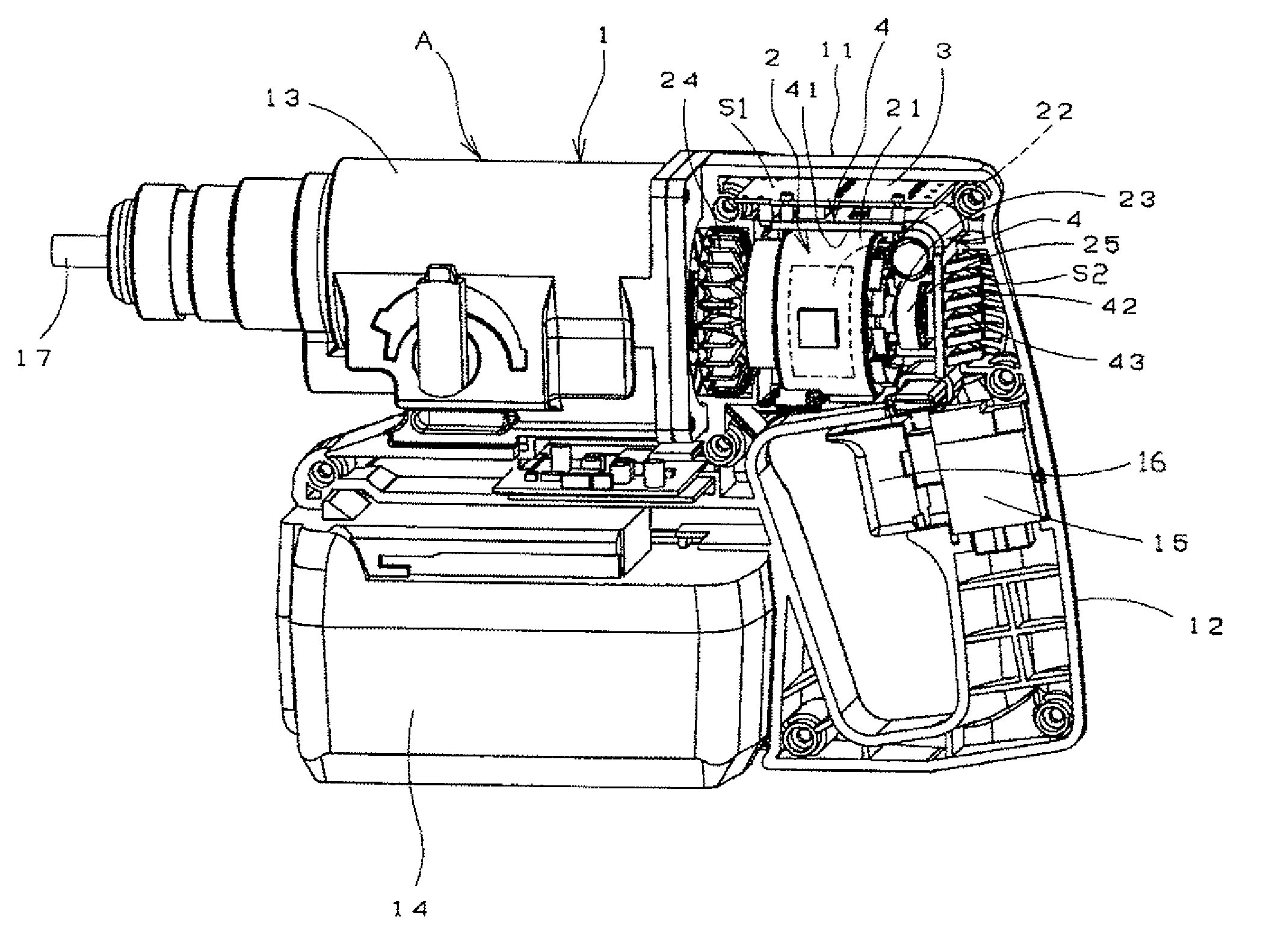
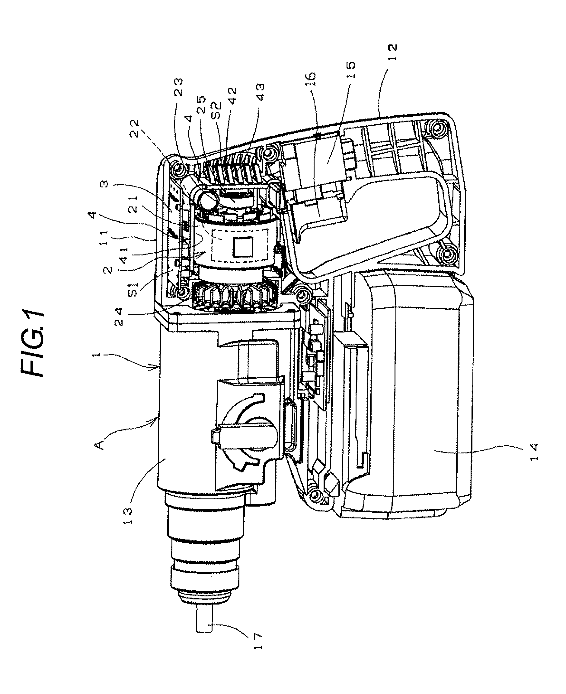
[0040]In FIG. 1, in the first space S1, there were provided a power substrate 3 for controlling the rotation of a brushless motor 2 and the heat sink main body 41 of a heat sink 4 for cooling the power substrate 3; and, in the second space S2, there is provided a heat releasing portion 42.

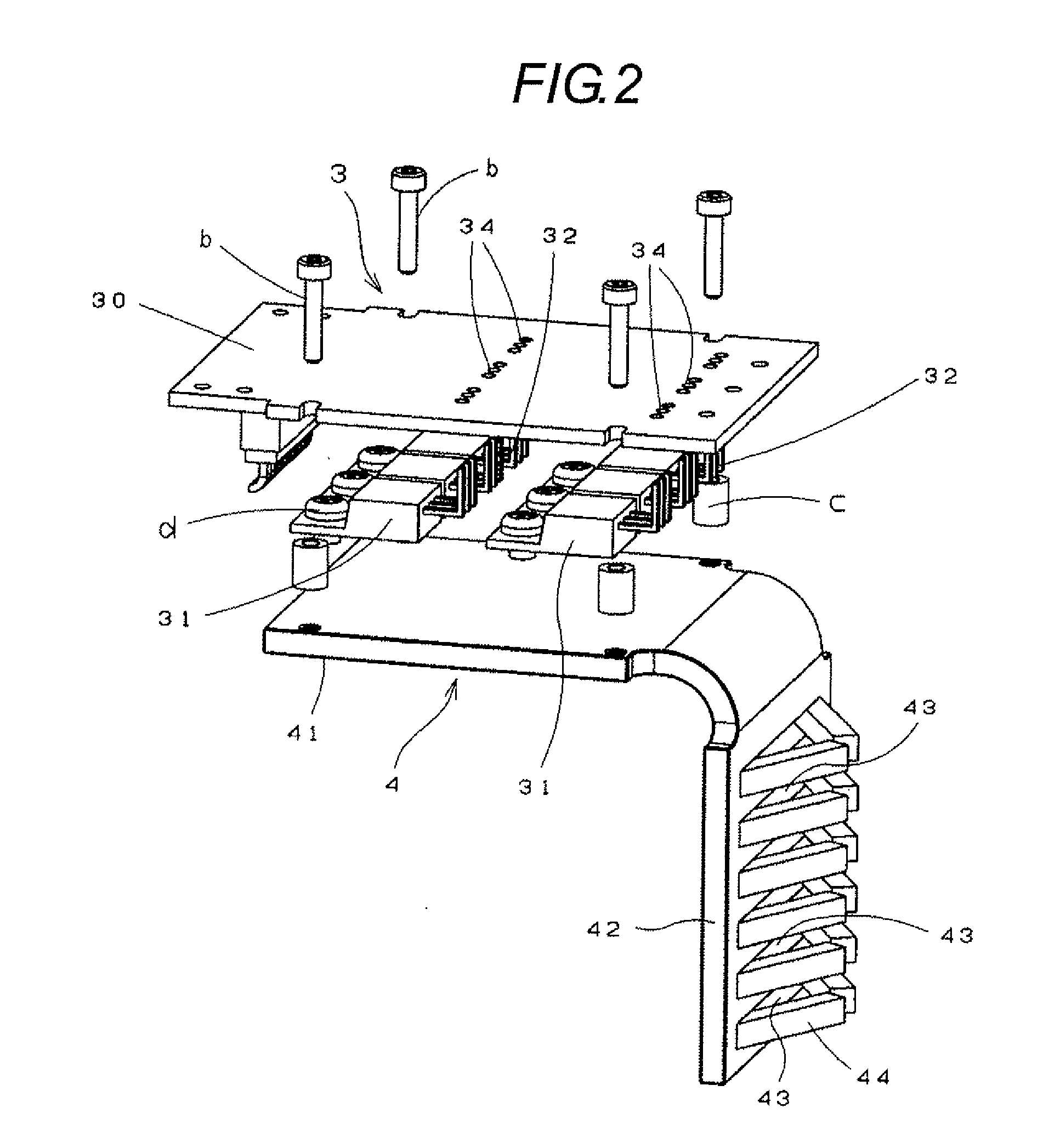
[0041]That is, as shown in FIG. 2, on the substrate portion 30 of the power substrate 30 that is made of insulating material, there are mounted integrally therewith six pieces of FETs 31 so as to correspond to three-phase windings (not shown) arranged on a stator (21). The FETs 31 are electronic parts for controlling the rotation of the brushless motor, and they are arranged in two lines in a direction perpendicular to the longitudinal direction of the substrate portion 30 of the power substrate 3, three FETs 31 in each line.

[0042]Each of the FETs 31 includes three electrodes, while the leg portions 32 of these electrodes are inserted into their associated rectangular-shaped holes 34 which are resp...

second exemplary embodiment

[0049]In FIG. 3, in the first space S1, there are arranged the connecting terminals (plug terminals) 6 of power wires for connecting together the power substrate 3 and a battery power supply included in a DC battery power pack 14 and lead wires for connecting together the power substrate 3 and the brushless motor 2. The lower (in FIG. 3) stages of the plug terminals 6 are the terminals of the power wires to be connected to the battery power supply, whereas the upper (in FIG. 3) stages thereof are the terminals of the lead wires to be connected to the power substrate 3 and brushless motor 2.

[0050]On the power substrate 3 necessary to drive the brushless motor 2, mainly, there are arranged the power wires from the battery power supply and the lead wires to the brushless motor 2. Since these wires respectively allow a large current to flow therein, they are formed thick and these wires are connected together directly using the plug terminals 6 and the like, which makes it necessary to ...


PUM


Abstract

In a first space S1 formed upwardly of a brushless motor, there is arranged a power substrate 3 including an electronic part for controlling a rotation of the brushless motor, and, in a second space S2 formed backwardly of the brushless motor, there is arranged a heat sink for cooling the power substrate 3.

Description

TECHNICAL FIELD[0001]The present invention relates to a power tool with a brushless motor and, specifically, the invention relates to a power tool which uses efficiently a structural characteristic of a power tool with a brushless motor carried thereon.BACKGROUND ART[0002]Most of motors for use in a power tool are of a type which is driven from a DC supply and, as an example of this type of motors, there is known a brushless motor which does not use a brush or a commutator. The brushless motor, instead of using a brush or a commutator, includes a power substrate and a control substrate which are respectively used to control a rotation of the brushless motor. On the power substrate, there is mounted an FET or the like which is an electronic part for controlling the rotation of the brushless motor.[0003]However, rotation controlling electronic parts are easy to generate heat, when the motor is driven. Thus, when the driving of the motor is kept ON, the electronic parts are overheated ...

Claims


Application Information

Patent Timeline
IPC IPC(8): H02K7/14
CPCB25D16/00H02K11/0073H02K7/145B25F5/008H02K11/33
Inventor SAKAMAKI, KAZUYATERANISHI, AKIRAKATOU, KOUJIARAI, KENICHI
Owner MAX CO LTD
Why Eureka
Try Eureka