Detection apparatus and method for superconducting coil quench

a superconducting coil and detection apparatus technology, applied in the direction of superconducting magnets/coils, instruments, magnetic bodies, etc., can solve the problems of noise in the voltage of the subject of monitoring, ground may become problems, and high frequency noise to be generated in the winding current, etc., to achieve high reliability

Active Publication Date: 2010-10-07
MITSUBISHI HEAVY IND LTD
View PDF9 Cites 23 Cited by
  • Summary
  • Abstract
  • Description
  • Claims
  • Application Information

AI Technical Summary

Benefits of technology

[0014]During the hold period where the energy of the superconducting coil is held, the noise on the balance voltage for detecting the resistance of the superconducting coil is small, so that the influence due to a voltage distribution by an inductance of the superconducting coil of the bridge circuit and an error variation of the resistance value of a voltage divider resistor is also small. By extracting the detection signal during this hold period and using this detection signal for judgment of a quench, it becomes possible to monitor and detect a quench with high reliability.
[0015]According to the present invention, a technique is provided, which makes it possible to detect a quench earlier while suppressing an influence due to the noise that is generated upon charging and discharging of a superconducting coil and a detection error in the bridge circuit under a condition of a high potential difference.

Problems solved by technology

In the SMES, a high frequency noise to be generated in a winding current due to switching of a converter and a leak current via a distributed capacitance between a coil and a ground may become problems.
On the other hand, according to the converter for carrying out charge and discharge in the SMES, due to a switching noise, an inductance of a coil, and a difference in a distributed capacitance in the inside of the SMES and the ground, a potential difference of the subject of monitoring becomes to have variations upon charging and discharging, and this causes a noise in a voltage of the subject of monitoring.
This noise makes it difficult to detect an abnormality with high accuracy.

Method used


Image

  • Detection apparatus and method for superconducting coil quench
  • Detection apparatus and method for superconducting coil quench
  • Detection apparatus and method for superconducting coil quench

Examples


Embodiment Construction

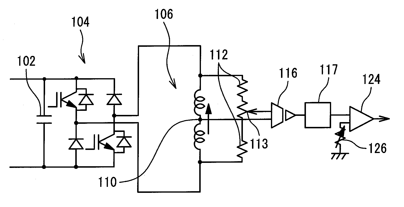
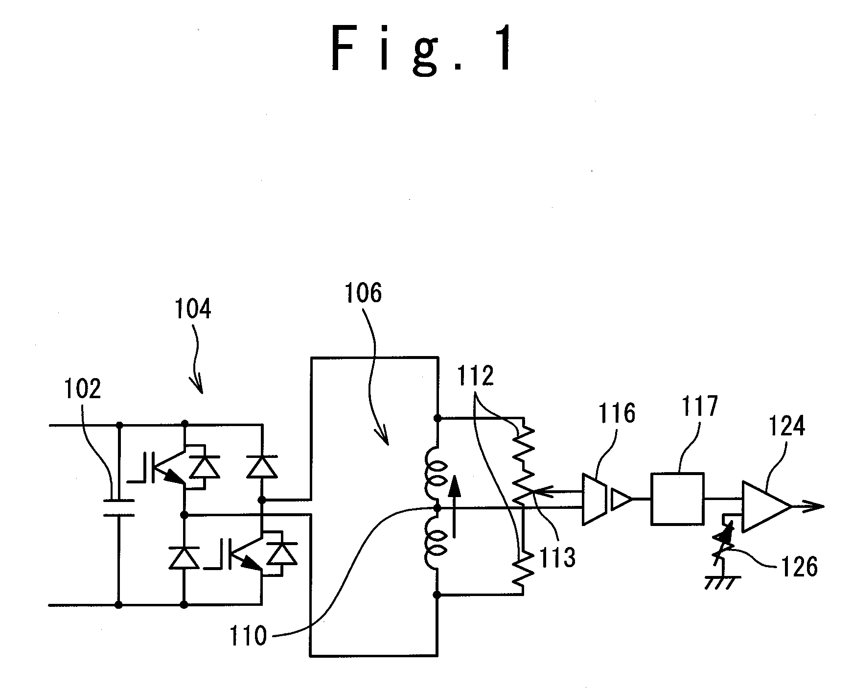
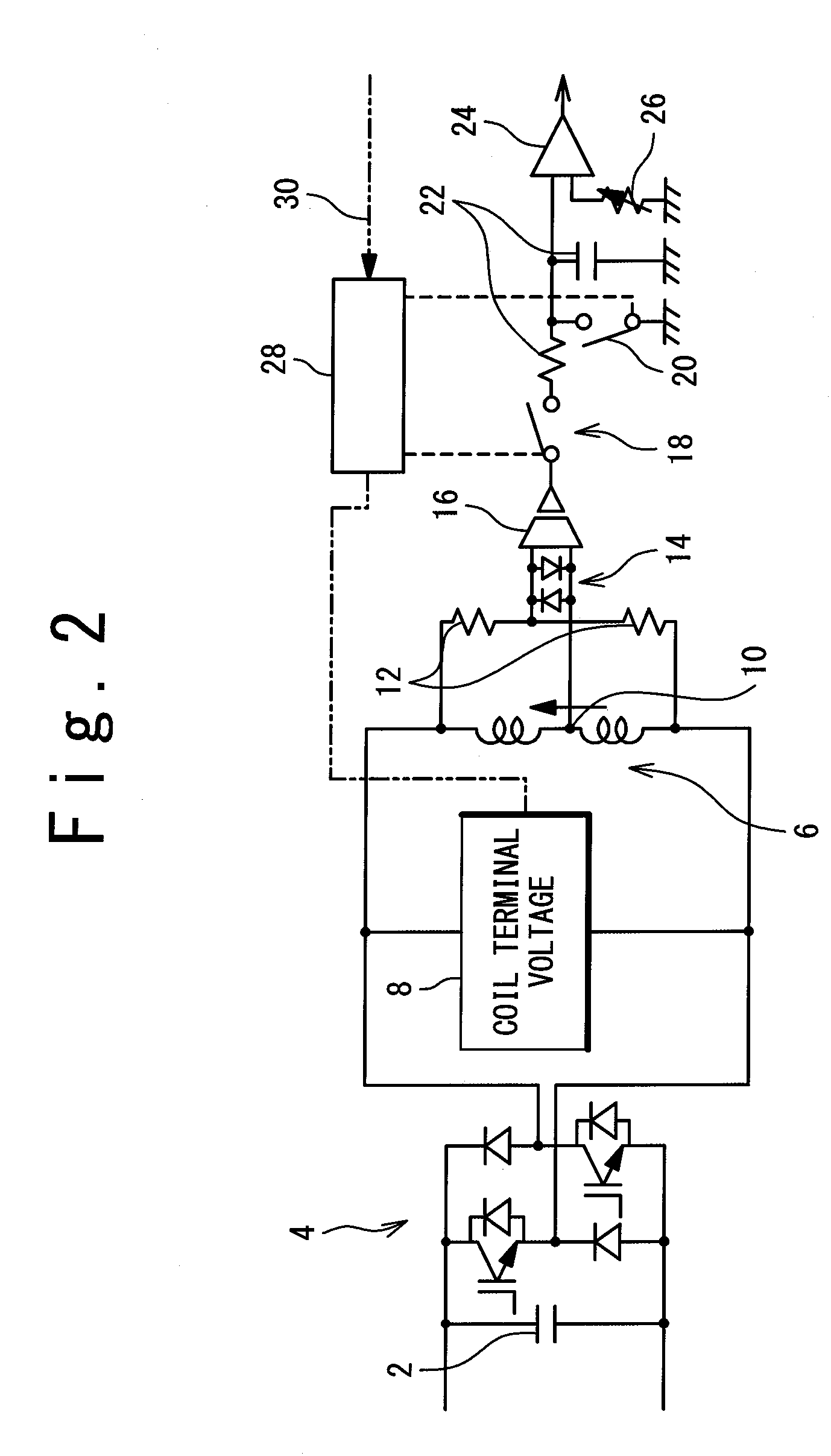
[0022]Referring to the accompanying drawings, embodiments according to the present invention will be described below. A quench detection circuit according to the present embodiment is used for monitoring and detecting a quench of a superconducting coil to accumulate energy in a SMES. In the superconducting coil of the SMES, it is difficult to judge whether or not a quench occurs on the basis of the absolute value of a terminal voltage of the superconducting coil since the coil current is always varied and further, this superconducting coil charges and discharges an electric current to and from a high voltage power source. Therefore, a bridge circuit is formed by connecting a resistor for detecting the voltage at a middle point in parallel to a pair of coils having a same specification placed in one current circuit, and the imbalance voltage of the bridge circuit is used as a signal for detecting a quench.

[0023]FIG. 2 illustrates the quench detection circuit according to the present ...


PUM


Abstract

The quench of the superconducting coil is desired to be detected early while suppressing the influences of the noise generated in charge and discharge of the superconducting coil. A superconducting coil quench detection apparatus detects the balance voltage of a bridge circuit formed by the superconducting coil and a resistor to output it as a quench detection signal for detecting the quench thereof. A signal indicating the hold period where the energy accumulated in the superconducting coil is held is generated. A signal included in the hold period is extracted from the quench detection signal. The quench of the superconducting coil is detected based on the extracted signal.

Description

INCORPORATION BY REFERENCE[0001]This patent application claims a priority on convention based on Japanese Patent Application No. 2008-289982. The disclosure thereof is incorporated herein by reference.TECHNICAL FIELD[0002]The present invention relates to a detection apparatus and method for superconducting coil quench.BACKGROUND ART[0003]In a superconducting coil, when the temperature or the electric current or the like do not meet certain requirements to maintain the superconducting state, the so-called quench occurs and the superconducting state is shifted to the non-superconducting state. When the quench occurs, the resistance value is increased at the part where the quench occurs, and then, rapid conversion into the thermal energy occurs due to the electric current. In order to protect superconducting material and insulating material and prevent damages thereof when the quench occurs, earlier detection of the quench is desired.[0004]In a direct current magnet that is formed by s...

Claims


Application Information

Patent Timeline
Patent Type & Authority Applications(United States)
IPC IPC(8): G01R27/08G01R31/50
CPCG01R31/024G01R33/1246Y02E40/68H02H7/001H01F6/02Y02E40/60G01R31/50
Inventor KAWASHIMA, HIROSHI
Owner MITSUBISHI HEAVY IND LTD
Why Eureka
Try Eureka