
Method and apparatus for aligning microbeads in order to interrogate the same

a technology of microbeads and interrogation, which is applied in the field of methods and apparatus for processing information contained on microbeads, can solve the problems of insufficient different codes, inability to withstand harsh temperature, chemical, nuclear and/or electromagnetic environments, and insufficient existing technologies such as bar codes, to achieve reliable and repeatable transportation of all beads, and low cost. , the effect of fast and effective/reliable movemen

Inactive Publication Date: 2010-10-07
ILLUMINA INC
View PDF99 Cites 13 Cited by
  • Summary
  • Abstract
  • Description
  • Claims
  • Application Information

AI Technical Summary

Benefits of technology

[0015] The invention provides a method for aligning the microbeads in the two rotational axes to a fixed orientation relative to an incident laser beam and a readout camera, otherwise known as the code camera. The invention further provides a method for rapidly aligning a large number of microbeads, between 1,000 and 1,000,000 microbeads or more, economically, and with the necessary tolerances. The method is flexible as it relates to the size of the microbeads and can be integrated into a fully automated system, which prepares the microbeads for rapid readout by an automated code-reading machine.
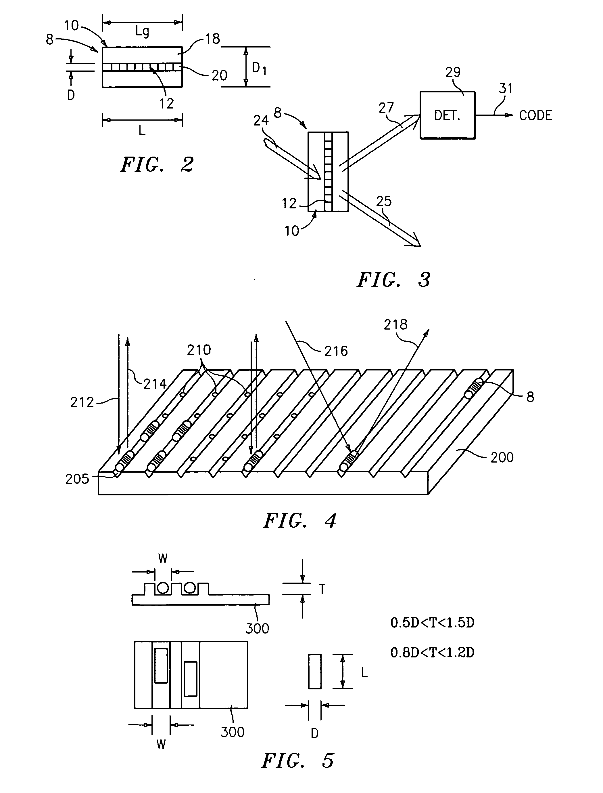
[0016] In one embodiment of the present invention, the positioning device includes a plate with a series of parallel grooves (or channels), which could have one of several different shapes, including square, rectangular, v-shaped, semi-circular, etc., as well as a flat bottom groove with tapered walls. The grooves are formed into an optically transparent medium such as boro-silicate glass, fused silica, or other glasses, or plastic or other transparent support materials. The depth of the grooves will depend on the diameter of the microbead but generally they will be between 10 and 125 μm, but may be larger as discussed hereinafter, depending on the application. The spacing of the grooves is most optimal when it is between 1 and 2 times the diameter of the microbead, providing for both maximum packing density as well as maximum probability that a microbead will fall into a groove. The width of grooves is most optimal when the gap between the microbead and the walls of the grooves is sufficiently small to prevent the microbeads from rotating within the grooves by more than a few degrees. The bottom of the groove must also be maintained flat enough to prevent the microbeads from rotating, by more than a few tenths of a degree, relative to the incident laser beam. Another critical aspect of the grooved plate is the optical quality of the grooves. To prevent excess scatter of the readout laser beam, which could lead to low contrast between the code signal and the background scatter, it is important that the grooves exhibit high optical quality. The beads can be read in the groove plate from below, on top of, or the side of the plate, depending on the application and type of microbead used.
[0019] Once the microbeads are aligned, they can be read as many times as necessary to get a good reading or improve statistics.
[0021] Microbeads can be mixed after reading then re-read to enhance the statistics of readout process.
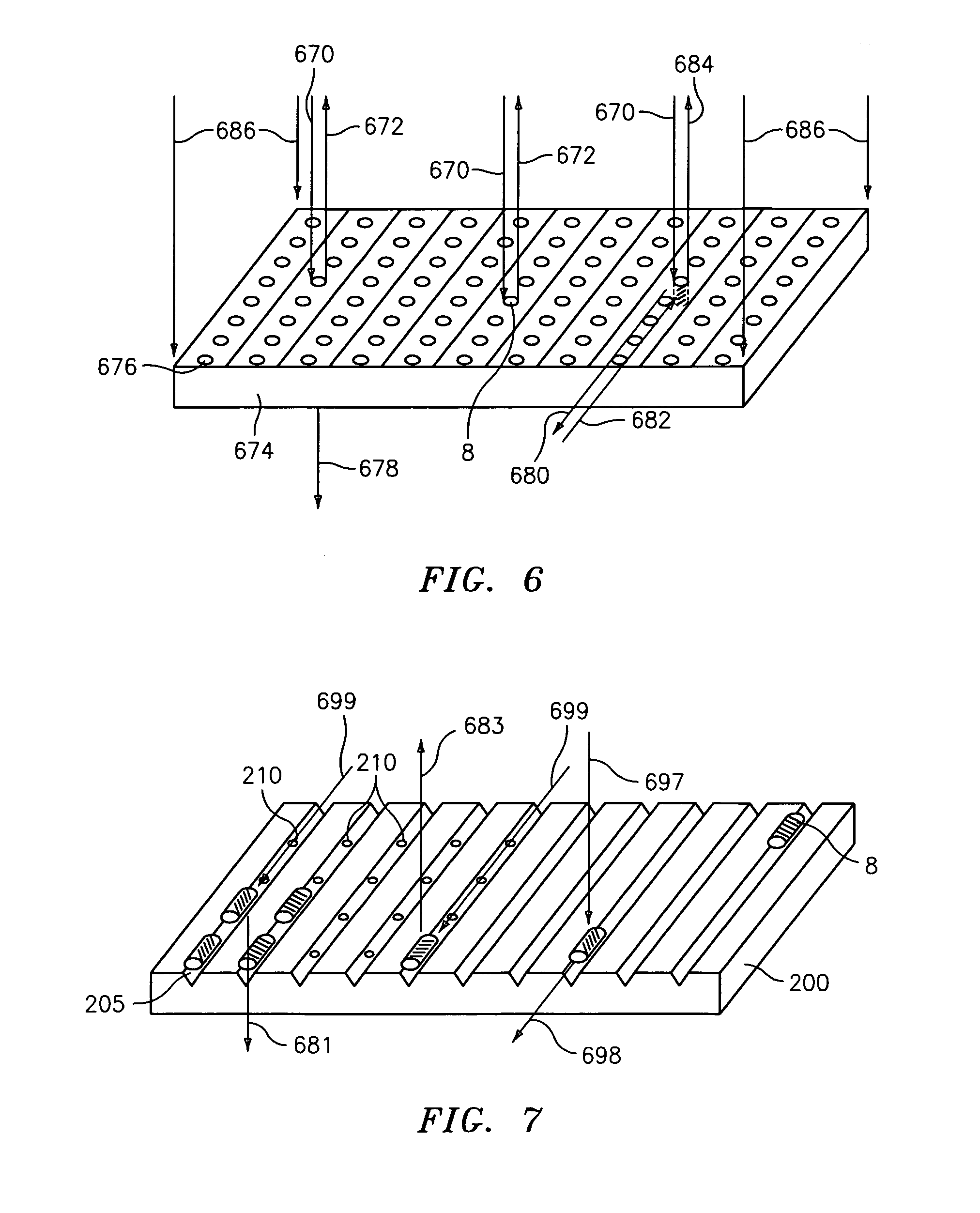
[0029] The invention is a significant improvement over prior art bead movement techniques in being able to repeatably move a predetermined number of beads from one location (or container or well) to another location (or container or well). Also, the invention provides for the reliable and repeatable transportation of all beads from one container or well to another or from one well to multiple wells using a “telegraph” technique. The invention is useful for creating multiplexed bead kits having a required number of beads of each code in a kit. The present invention may also be used to move the beads from a container to a reader to allow for the bead codes and / or chemistry on the beads to be read. The invention may be used in any assay or multiplexed experiment, combinatorial chemistry or biochemistry assay process, or in a taggant application, or any other application where beads are in a liquid solution and need to be transported, kitted and / or read.
[0030] Advantages of the “telegraph” technique of the present invention are that it is low cost, fast, effective / reliable for moving beads, and low precision is required. Advantages of the pipetting techniques of the present invention is that the pippeter is a standard off the shelf product, it is flexible to be used with any type of well or container (e.g., sizes, shapes and other characteristics), or other fluid configurations, and does not require any sealing or physical connections to the wells.

Problems solved by technology

Existing technologies, such as bar codes, electronic microchips / transponders, radio-frequency identification (RFID), and fluorescence and other optical techniques, are often inadequate.
For example, existing technologies may be too large for certain applications, may not provide enough different codes, or cannot withstand harsh temperature, chemical, nuclear and / or electromagnetic environments.
One challenge in transporting microbeads is being able to move them reliably from one location to another reliably and / or being able to move a predetermined number of beads.

Method used


Image

  • Method and apparatus for aligning microbeads in order to interrogate the same
  • Method and apparatus for aligning microbeads in order to interrogate the same
  • Method and apparatus for aligning microbeads in order to interrogate the same

Examples


Embodiment Construction

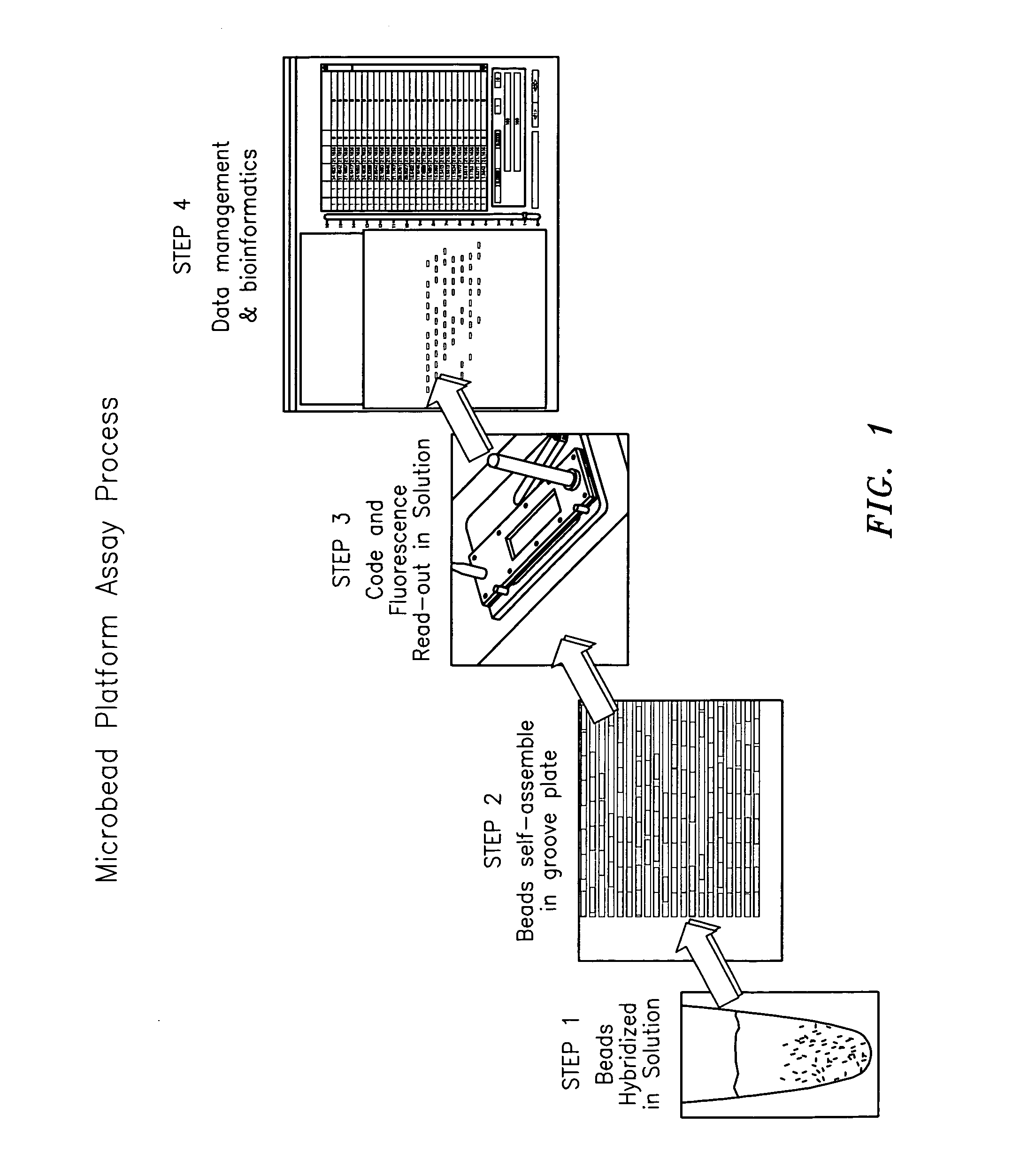
[0089]FIG. 1 shows, by way of example, steps of a microbead assay process which uses the microbead technology of the present invention. The steps of the assay process shown in FIG. 1 include a first step in which the microbeads are used in a solution; a second step in which the microbeads are aligned in a desired manner; a third step in which the code and florescence in and / or on the microbeads are read-out; and a fourth step in which the information related to the code and florescence is processed in relation to data management and bioinformatics. The present invention primarily relates to step 2 wherein the microbeads are uniquely aligned so the longitudinal axis of the microbeads is positioned in a fixed orientation relative to the code and florescence reading device, as well as relating to a lesser extent to step 3. It is important to note that the scope of the present invention is not intended to be limited to any particular type or kind of assay process or other process in whi...


PUM

PropertyMeasurementUnit
diameteraaaaaaaaaa
diameteraaaaaaaaaa
photosensitiveaaaaaaaaaa

Abstract

A method and apparatus are provided for aligning optical elements or microbeads 8, wherein each microbead has an elongated body with a code embedded therein along a longitudinal axis thereof to be read by a code reading device. The microbeads 8 are aligned with a positioning device (or cell) 500 having a plate or platform 200, 1252 with grooves 205, 1258 so the longitudinal axis of the microbeads is positioned in a fixed orientation relative to the code reading device. The microbeads 8 are typically cylindrically shaped glass beads having a diffraction grating-based code embedded in the bead 8 disposed along an axis, which requires a predetermined alignment between the incident code readout laser beam and the code readout detector in two of three rotational axes. The geometry of the grooves 205 are designed to allow for easy loading and unloading of beads from a cell, and the grooves 205 may be straight or curved. Also, the cell may be segmented into regions each associated with a different reaction or used for a different identification process / application, and may have many different geometries depending on the application.

Description

CROSS REFERENCES TO RELATED APPLICATIONS [0001] The present application claims the benefit of: U.S. Provisional Application Ser. No. 60 / 609,583, filed Sep. 13, 2004, entitled “Improved Method and Apparatus for Aligning Microbeads in Order to Interrogate Same” (Docket No. CV-0082 PR); Ser. No. 60 / 610,910, filed Sep. 17, 2004, entitled “Method and Apparatus for Aligning Microbeads in Order to Interrogate Same” (Docket No. CV-0086 PR); and Ser. No. 60 / 610,833, filed Sep. 17, 2004, entitled “Method and Apparatus for Transporting and Kitting Microbeads” (Docket No. CV-0087 PR); and is a continuation-in-part of: U.S. patent application Ser. No. 10 / 661,836, filed Sep. 12, 2003, entitled “Method And Apparatus For Aligning Microbeads In Order To Interrogate The Same” (Docket No. CV-0042), and Ser. No. 11 / 063,665, filed Feb. 22, 2005, entitled “Multi-well Plate with Alignment Grooves for Encoded Microparticles” (Docket No. CV-0053 US), all the above of which are incorporated herein by referen...

Claims


Application Information

Patent Timeline
Patent Type & Authority Applications(United States)
IPC IPC(8): G01N1/00
CPCB01J2219/00459Y10T436/25B01J2219/00466B01J2219/0047B01J2219/005B01J2219/00545B01J2219/00547B01J2219/00576B01J2219/00648B01J2219/00657B01J2219/00659B01J2219/00702B01L3/502761B01L3/5085B01L2200/0636B01L2200/0668B01L2300/0654B01L2400/0409B01L2400/0457B01L2400/0487G01N15/147G01N35/00732G01N2035/00574G01N2035/00782G03H1/0272G03H2210/53G03H2230/10G03H2270/20G03H2270/24Y10T436/2575B01J2219/00463
Inventor PUTNAM, MARTIN A.LEMOINE, RICHARD L.
Owner ILLUMINA INC
Learn More