Polymer spring controlled pulley assembly for rotary devices

a technology of rotary devices and pulleys, which is applied in the direction of yielding couplings, gearing elements, hoisting equipments, etc., can solve the problems of conventional belt tensioners, inability to compensate, and the rotation of the crankshaft of an internal combustion engine, so as to reduce the impact of velocity changes, and reduce the speed differential

Inactive Publication Date: 2010-10-07
CT DRIVES LLC A LIMITED LIABILITY COMPANY OF THE STATE OF CALIFORNIA
View PDF7 Cites 28 Cited by
  • Summary
  • Abstract
  • Description
  • Claims
  • Application Information

AI Technical Summary

Benefits of technology

[0009]In accordance with one aspect, the invention provides a drive system for a rotary device having a driven shaft that is coupled to a pulley. A hub is connected to the shaft and journaled within the pulley to rotatably support the pulley. The hub and pulley are coupled by a plurality of solid resilient polymer spring members that are disposed between interleaved projections formed on facing surfaces of the pulley and the hub. The polymer spring members allow resilient relative bidirectional rotation of the pulley and hub over a predetermined range of angular rotations such that sudden bidirectional relative rotational velocity changes due to accelerations and decelerations of the pulley and the hub are cushioned by providing an increasing torque over said predetermined range to smoothly reduce the velocity differential and attenuate the impact of the velocity changes on the shaft.
[0010]In another aspect, the invention affords a drive system for a rotary device comprising a pulley and a hub journaled within the pulley and connected to a shaft of the rotary device. The pulley and hub are formed with first and second pluralities of interleaved radially extending projections that form a plurality of cavities therebetween. A plurality of solid polymer spring members are disposed within corresponding cavities, and are arranged to be deformed by the projections upon relative angular rotation of the pulley and the hub due to sudden rotational velocity changes. The drive system operates bidirectionall

Problems solved by technology

The rotation of an internal combustion engine crankshaft is, however, subject to perturbations, the magnitude and frequency of which varies with engine RPM.
Conventional belt tensioners react to these dynamic fluctuations but cannot compensate for them.
The fluctuations are transmitted to the shafts of the rotary devices through their pulleys, and may produce undesirable belt slippage, noise and vibration that are transmitted to a passenger compartment, as well as cause wear and tear on the rotary devices.
This results in higher than desirable belt wear and shortens the life of the rotary devices.
Automotive alternators are particularly susceptible to increased wear and decreased life due to such fluctuations because of their high inertia and high speed, and they tend to fail frequently.
However, one-way clutches do not satisfactorily accommodate abrupt increases in speed, as when combustion occurs, since th

Method used


Image

  • Polymer spring controlled pulley assembly for rotary devices
  • Polymer spring controlled pulley assembly for rotary devices
  • Polymer spring controlled pulley assembly for rotary devices

Examples


Embodiment Construction

[0023]The invention is particularly well adapted for use in automotive applications and will be described in that context. It will be appreciated, however, that this is illustrative of only one utility of the invention, and that the invention has broader applicability to other applications. As will be appreciated from the description which follows, the invention advantageously reduces noise and vibration in applications and systems which employ rotating prime movers or drivers, such as internal combustion engines or the like, that are characterized by pulsed rotational variations or velocity perturbations, and rotary devices driven by the prime movers.

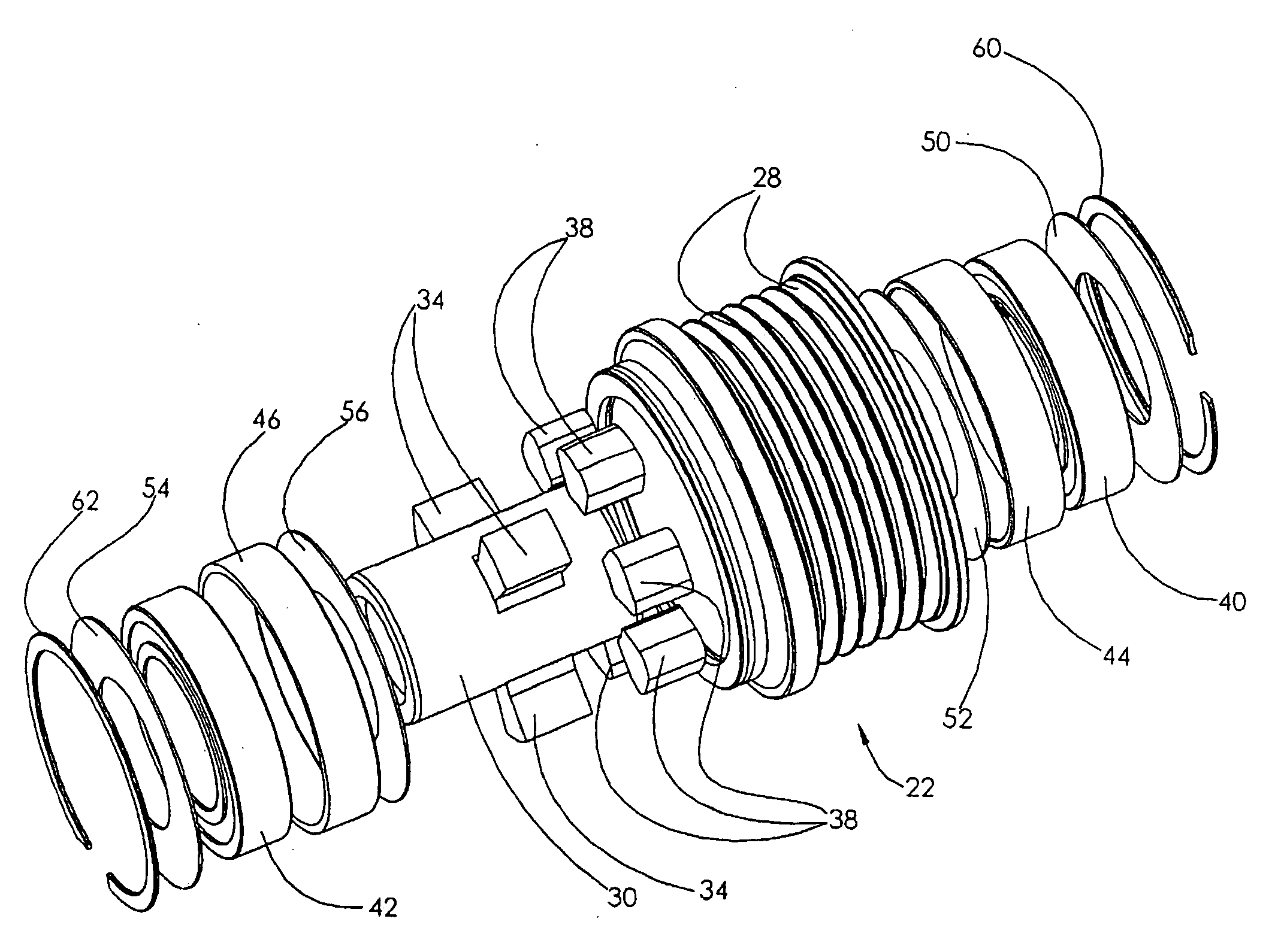
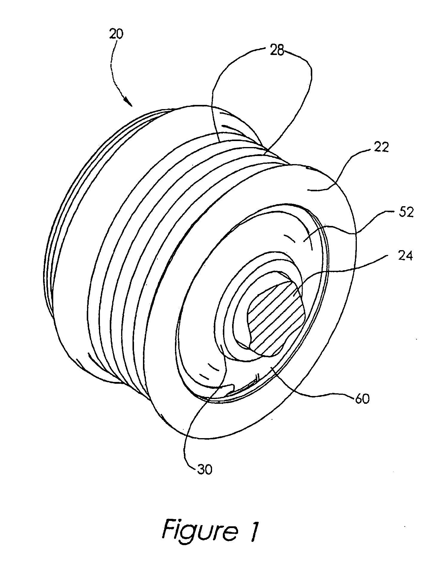
[0024]FIG. 1 shows a perspective view of a pulley assembly 20 comprising a pulley 22 and a drive system in accordance with the invention. The pulley assembly is adapted to be located on the end of a drive shaft 24 of a rotating device, such as an automotive alternator (not illustrated), and to be driven in a well known manner by a driv...


PUM


Abstract

A drive system for a rotary device, such as an automotive alternator compensates for and reduces the effect of sudden bidirectional rotational velocity variations of the pulley caused by sudden acceleration and deceleration of an internal combustion engine without using a one-way clutch. The drive system comprises a pulley comprising a tubular barrel having a plurality of radial projections extending inwardly from its inner surface, and a cylindrical hub that is journaled within the pulley and connected to the alternator shaft. The hub has a plurality of radial projections extending outwardly from its outer circumference which are interleaved between the pulley projections. A plurality of solid resilient polymer spring members are disposed in the cavity spaces between the projections. Upon sudden acceleration or deceleration of the pulley, it rotates angularly relative to the hub and shaft to resiliently compress the polymer spring members, which exert a counter restoring force to eliminate the relative angular rotation.

Description

BACKGROUND[0001]This invention relates generally to drive systems for rotary devices, and more particularly to pulley assemblies for rotary automotive accessory devices such as alternators.[0002]Some systems which employ rotary prime movers as drivers for providing rotational motive power for driving rotary accessory devices are characterized by dynamic loading and inertial torque characteristics which result in rotational perturbations that are transmitted to the accessory devices. An example of such systems is an internal combustion engine that drives rotary accessory devices such as an alternator, air-conditioning compressor, water pump, etc. Rotation of the engine crankshaft is transmitted via a serpentine or poly-V belt system or conventional V-belt systems to pulleys attached to the drive shafts of such accessory devices to rotate their shafts. In some cases the mechanical connection between crankshaft and the accessory device is a gear train. The rotation of an internal combu...

Claims


Application Information

Patent Timeline
IPC IPC(8): F16H55/48
CPCF16H2055/366F16H55/48F16D3/68
Inventor CALI, CONNARDFITZ, FRANK A.FERREIRA, CARLOS
Owner CT DRIVES LLC A LIMITED LIABILITY COMPANY OF THE STATE OF CALIFORNIA
Why Eureka
Try Eureka