
Intraocular Lens Injector with Hydrophilic Coating

Inactive Publication Date: 2010-10-07
BAUSCH & LOMB INC
View PDF21 Cites 28 Cited by
  • Summary
  • Abstract
  • Description
  • Claims
  • Application Information

AI Technical Summary

Benefits of technology

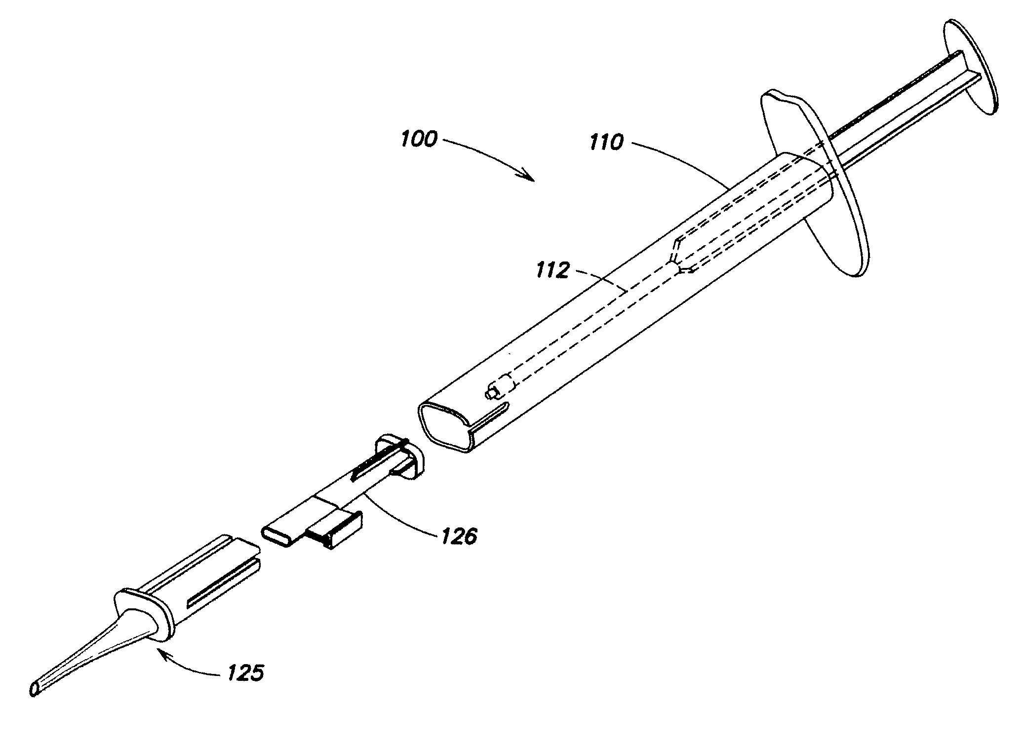
[0008]An injector includes one or more polymeric portions that include a hydrophilic coating component that is effective to facilitate the passage of the IOL through the injector, particularly the passage of the IOL through the injector tip. The degree of lubricity can be conveniently controlled by the selection of the hydrophilic coating component as well as the concentration of the hydrophilic component at the surface. Also, the hydrophilic coating component is stable on a long term basis, that is, the injector has a relatively long shelf life.
[0009]The IOL injector is prepared by a process that includes irradiating at least a portion of a polymeric, IOL injector with UV light in an environment comprising oxygen to provide a positive percent change in the atomic oxygen content of the polymer material at the surface as determined by X-ray Photoelectron Spectroscopy (XPS). A portion of or the entire irradiated portion is contacted with a solution comprising a hydrophilic coating component. The hydrophilic coating component is selected from a hydrophilic polymer, a hydrophilic copolymer or any one mixture thereof to provide a solution coated portion. The solution coated portion is heated at a temperature to provide portions of the IOL injector with a shelf-stable, lubricious hydrophilic coating to facilitate delivery of an IOL from the injector with minimal damage to the lens and with little or no transfer of the hydrophilic coating to a surface of the lens.
[0010]The use of the IOL injector allows successful ocular implantation of various IOL materials such as hydrophobic acrylics, hydrophilic acrylics as well as silicone-based materials. The IOL injector allows the surgeon to implant an IOL through incisions of about 3.0 mm or less, preferably about 2.6 mm or less, and even as small as about 2.2 mm or less.

Problems solved by technology

Should an IOL be damaged or released from the injector in an incorrect orientation, a surgeon may need to remove the IOL.
A problem arises, however, as the surgeon demands even smaller incision sizes and / or the design complexities of the IOL inhibits an efficient folding of the lens.
For example, the material from which the injector tube or tip is made, for example, polypropylene and the like polymeric materials, may not be compatible or suitable for passing a tightly folded IOL through an injector opening of sufficient size to fit within the incision.
Often attempts to force an IOL through an injector with insufficient lubricity will lead to damage of the IOL during delivery.

Method used


Image

  • Intraocular Lens Injector with Hydrophilic Coating
  • Intraocular Lens Injector with Hydrophilic Coating
  • Intraocular Lens Injector with Hydrophilic Coating

Examples


examples

Irradiation Apparatus

[0037]The AI28 and AI20 inserter t-cells, which are manufactured by Bausch & Lomb, Inc., were exposed to high energy UV-C light using an irradiation apparatus. The UV irradiation apparatus is a UVO-CLEANER® Model 342 manufactured by Jelight Company, Inc. of Irvine, Calif. The UV irradiation apparatus 40 resembles an electric broiler with the UV lamp assembly 46 along the top side and a sliding drawer 42 equipped with a sample tray 44 (shown in open position). The t-cells are placed in the tray approximately six inches from the lamp assembly. The UV irradiation source is a low pressure mercury vapor grid with an output of 28,000 μW / cm at 254 nm (at 6 mm). The t-cells were exposed to this light in air or a flow of dioxygen for 12 minutes.

X-ray Photoelectron Spectroscopy (XPS) Apparatus

[0038]A Physical Electronics Quantum 2000 Scanning ESCA Microprobe was used for the surface characterization of the t-cell before (control cells) and following UV irradiation. This i...

example 22 to 24

[0043]UV-C treated AI20 t-cells were coated with three different concentrations (Ex. 22, 10%; Ex. 23, 15%; and Ex. 24, 20%) of (60:40) PVP-vinyl acetate copolymer solution as described above. The injection force required to deliver Akreos MI-60 IOL was measured using an Instron test system. T-cells were not sterilized for this study. +20.0 D lenses and Amvisc Plus viscoelastic was used for all lens deliveries. The force data reported in Table 4 indicates that Example 24, i.e., a coating solution of 20% (60:40) PVP:VA required the least amount of force to deliver a lens (a relatively low average peak injection force of 317 gm-f along with a tighter standard deviation of 16). An average 581 gm-f peak force is required to deliver standard +20D MI60 lenses with a GMS / PP AI20 system (control). Accordingly, UV-C treated AI20 t-cells coated with the solution of Example 24 exhibits a reduction in delivery force of about 45%.

TABLE 4additiveEx. No.Force gm-f, N = 5transferobservations22429 (7...

examples 25 to 27

[0044]An accelerated aging study was conducted to estimate the shelf-life of PVP:VA copolymer coated AI28 t-cells stored at 82° C. over 6 days (this simulates at least 1 year of room temperature performance based on the accelerated shelf life prediction equation: treal=tacc×2(Ta-22° C.) / 10, where Ta is the accelerated temperature and t is time. The t-cells were exposed to UV-C radiation and manually dip coated with a PVP:VA (60:40) copolymer coating as described previously. The coated parts were dried in an oven at 85° C. for 1 hour before aging in an oven at 82° C. Samples were tested at time 0, Day 3 (6 months RT) and Day 6 (12 months RT). Mid-power Akreos Adapt AO IOLs were used for testing lens deliveries. The 6-day test data reported in Table 5 shows that the coating was robust and performed exceptionally well under the aggressive test conditions.

TABLE 5coatingEx.coatingtransferNo.t-cell# trialscompositionratingobservations25AI28510% PVP-VAa05 smooth deliveries,no optic damage2...


PUM

PropertyMeasurementUnit
Temperatureaaaaaaaaaa
Fractionaaaaaaaaaa

Abstract

An IOL injector that includes one or more polymeric portions that include a hydrophilic coating component that is effective to facilitate the passage of the IOL through the injector, particularly an injector tip. The IOL injector is prepared by a process that includes irradiating at least a portion of a polymeric, IOL injector with UV light in an environment comprising oxygen to provide a positive percent change in the atomic oxygen content of the polymer material at the surface as determined by X-ray Photoelectron Spectroscopy (XPS). A portion or the entire irradiated portion is then contacted with a solution comprising a hydrophilic coating component. The hydrophilic coating component is selected from a hydrophilic polymer, a hydrophilic copolymer or any one mixture thereof to provide a solution coated portion. The solution coated portion is then heated at a temperature to provide portions of the IOL injector with a shelf-stable, lubricious hydrophilic coating to facilitate delivery of an IOL from the injector.

Description

CROSS REFERENCE[0001]This application claims the benefit of Provisional Patent Application No. 61 / 167,220 filed Apr. 7, 2009 which is incorporated by reference herein.FIELD OF THE INVENTION[0002]The invention relates to an injector for implanting an intraocular lens into an eye of a patient, and to methods for making such injector. Portions of the injector include a hydrophilic coating component to facilitate the insertion of a foldable intraocular lens into an eye.BACKGROUND OF THE INVENTION[0003]IOLs are artificial lenses used to replace natural crystalline lenses of patients' when their natural lenses are diseased or otherwise impaired. IOLs may be placed in either the posterior chamber or the anterior chamber of an eye. IOLs come in a variety of configurations and materials. Various instruments and methods for implanting such IOLs in an eye are known. Typically, an incision is made in a patient's cornea and an IOL is inserted into the eye through the incision. In one technique, ...

Claims


Application Information

Patent Timeline
IPC IPC(8): A61F9/007G02B1/12
CPCA61F2/1664B05D3/063B05D5/04B29K2995/0092B29C59/16B29C59/165B29C2035/0827B05D5/08
Inventor JANI, DHARMENDRACHITRE, KAUSTUBH S.
Owner BAUSCH & LOMB INC
Learn More