Method and device for restraining movement of continuously traveling glass sheet

Inactive Publication Date: 2010-10-14
CORNING INC
View PDF17 Cites 22 Cited by
  • Summary
  • Abstract
  • Description
  • Claims
  • Application Information

AI Technical Summary

Benefits of technology

[0008]We have developed a pair of sheet restraining units on each of the first and second sides of the sheet, which can be installed above the score line. The sheet restraining unit functions in such a way that it restrains the sheet but complies with the sheet shape, i.e., having a clamping force sufficient to hold the sheet without forcing sheet shape change. It will not block sheet vertical motion and will allow the sheet to move in a horizontal plane. It will absorb the kinematic energy from the sheet while moving with the sheet and effectively dampen the sheet motion during separation and post separation. It will also hel

Problems solved by technology

On the other hand, over constraint of the sheet by fixed rollers can cause sheet breakage and sheet crackout during the scoring process.
Sheet motion produced by any of the above mechanisms, or any other m

Method used


Image

  • Method and device for restraining movement of continuously traveling glass sheet
  • Method and device for restraining movement of continuously traveling glass sheet
  • Method and device for restraining movement of continuously traveling glass sheet

Examples


Embodiment Construction

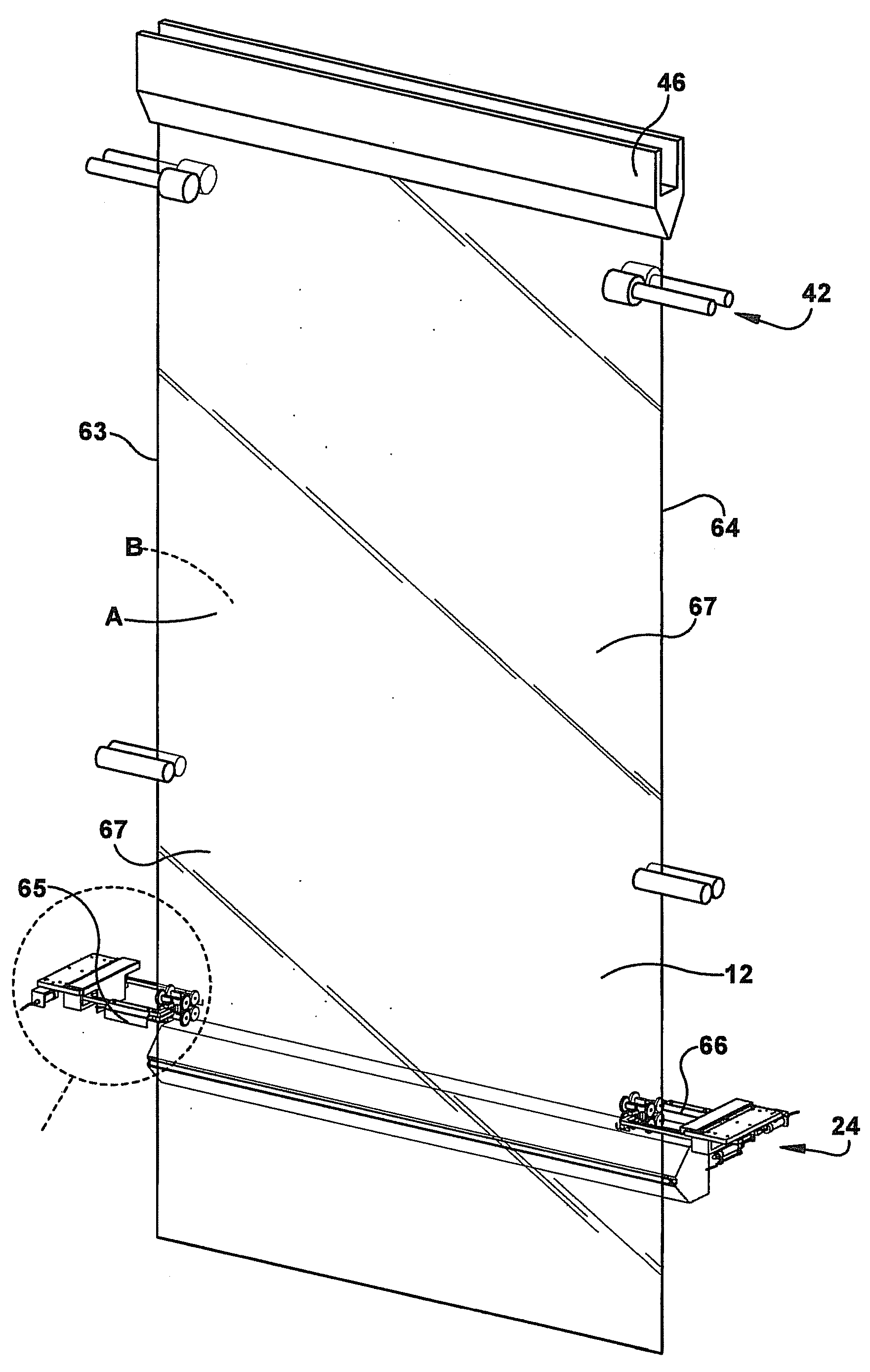
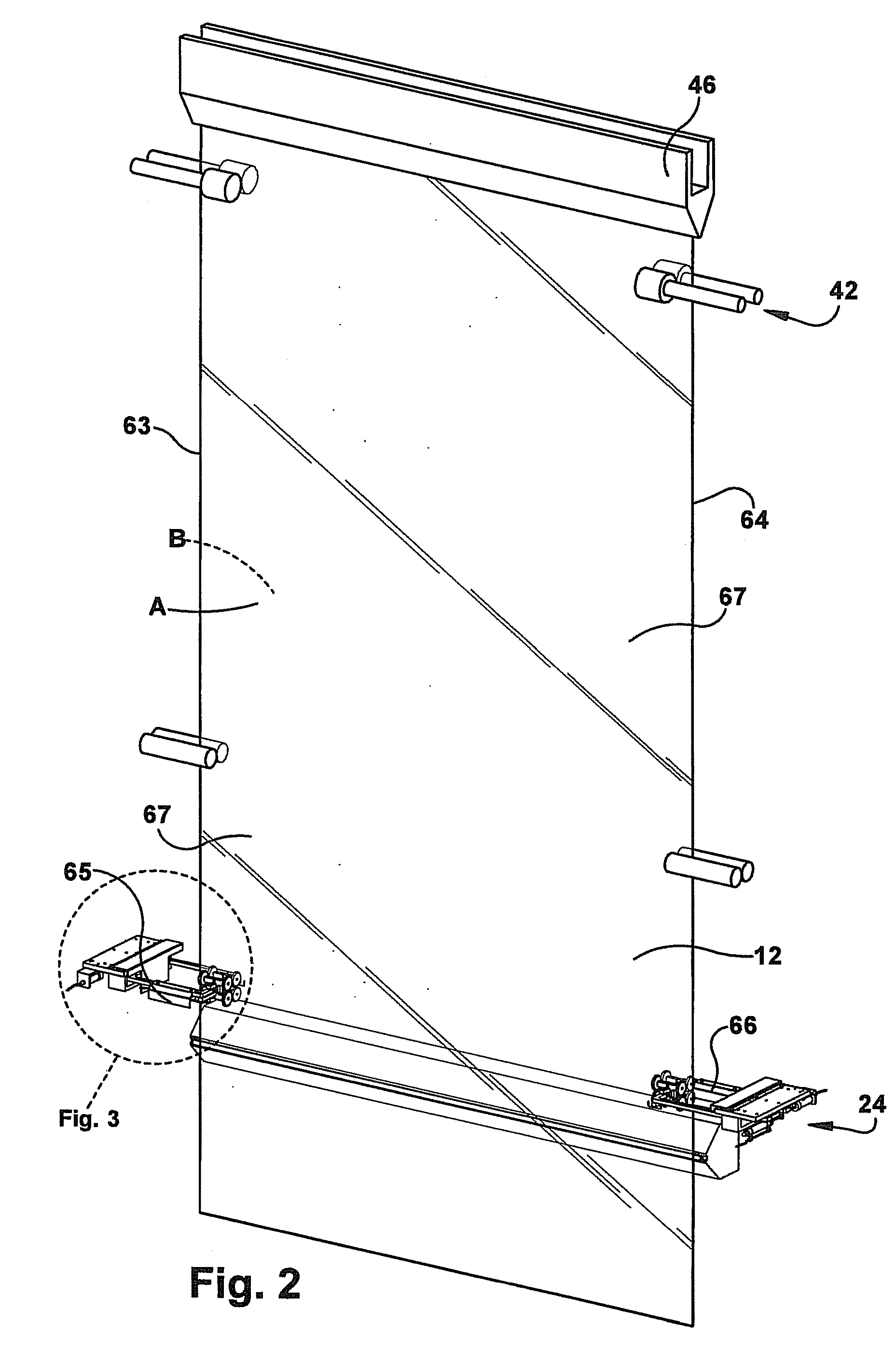
[0030]The sheet restrainers shown in the embodiment of FIGS. 2-5 are attached to TAM carriage 24 located above score line 62. The sheet restrainers are individual units, one on first side 63 of the glass sheet and the other on second side 64 of the sheet. Two sheet restrainer units 65, 66 are needed to restrain the sheet from both sides A, B (bead areas 67) once the sheet is clamped by each unit. Each unit includes two swing arms 68 movable about pivots 70 connected to frame 72 mounted to the TAM. Each swing arm 68 includes a main arm or first arm portion 74 and an angular control arm or second arm portion 76. Main arm 74 moves about pivot 70 and has an end 78 proximal to the sheet and an end 80 distal to the sheet. Angular control arms 76 are pivotally mounted at pivots 77 to proximal end 78 of each main arm 74. Each unit (e.g., unit 65, FIG. 3) includes a set of four rollers (a pair of rollers 82, and a pair of rollers 84) in contact with\glass sheet 12 on each side (A, B) of the ...


PUM

PropertyMeasurementUnit
Forceaaaaaaaaaa
Shapeaaaaaaaaaa
Stress optical coefficientaaaaaaaaaa

Abstract

A sheet restrainer is used to restrain movement of continuously traveling glass sheet and includes arms on either side of the glass sheet. A driving device coupled to the arms moves the arms from a retracted position in which the arms are withdrawn from the glass sheet to an engaged position in which the arms are near the glass sheet and in alignment with each other. Rollers are connected to the arms and contact the glass sheet in the engaged position. A damping device applies an adjustable damping force to at least one of the arms dampening movement of the arm in the engaged position thereby restraining movement of the sheet. In a method of operation, the damping devices restrain angular and/or lateral movement of the sheet by transmitting movement of the sheet against the rollers into a resistive damping force of the damping devices.

Description

TECHNICAL FIELD[0001]The field is restraining movement of continuously traveling glass sheet during scoring and separation of the sheet.TECHNICAL BACKGROUND[0002]A fusion process (e.g., downdraw process) forms high quality thin glass sheets that can be used in a variety of devices such as flat panel displays. Glass sheets produced in a fusion process have surfaces with superior flatness and smoothness when compared to glass sheets produced by other methods. The fusion process is described below with respect to FIG. 1 (Prior Art) but for a more detailed description refer to co-assigned U.S. Pat. Nos. 3,338,696 and 3,682,609, which are incorporated herein by reference in their entireties.[0003]FIG. 1 shows a schematic view of an exemplary glass manufacturing system 10 which utilizes the fusion process to make a glass sheet 12. As shown, the exemplary glass manufacturing system includes melting vessel 14, fining vessel 16, mixing vessel 18, delivery vessel 20, fusion draw machine (FDM)...

Claims


Application Information

Patent Timeline
IPC IPC(8): B23Q3/02B23Q7/00
CPCC03B35/16C03B17/064Y10T29/49998B65G49/06C03B17/06C03B35/20
Inventor ZHOU, NAIYUETREICHLER, GEORGE DAVISZHU, ZEPEI
Owner CORNING INC
Why Eureka
Try Eureka