Closed-Loop Torque Phase Control for Shifting Automatic Transmission Gear Ratios Based on Friction Element Load Sensing

a technology of automatic transmission and phase control, applied in mechanical equipment, digital data processing details, instruments, etc., can solve the problems of deep and wide torque hole for inconsistent shift feel, inconsistent shift feel, and vehicle occupants' perception of shift shock, so as to reduce engine flair and shift shock, increase torque capacity, and reduce torque capacity

Active Publication Date: 2010-10-14
FORD GLOBAL TECH LLC
View PDF36 Cites 34 Cited by
  • Summary
  • Abstract
  • Description
  • Claims
  • Application Information

AI Technical Summary

Benefits of technology

[0022]The present invention is directed to a closed loop shift control apparatus and method based on friction element load level that controls on-coming friction element engagement and off-going friction element release process during a torque phase of gear ratio changing from a low gear configuration to a high gear configuration for an automatic transmission system. Pressure actuated torque establishing elements define torque flow paths in transmission gearing as they are selectively engaged and released. Direct measurements or estimates of torsional load exerted onto an off-going friction element and direct measurements or estimates of on-coming friction element engagement torque are used to improve shift feel. In a first embodiment the measurements of torsional load are used to predict an optimal off-going friction element release timing for achieving a consistent shift feel. The ideal timing to release the off-going friction element, is uniquely defined when the torque load exerted onto the off-going friction element becomes zero or a near-zero level. The measurements or estimates of on-coming friction element engagement torque level are used in a closed-loop control method to closely follow a given target trajectory for achieving a consistent shift feel.
[0024]The system for controlling a multiple-ratio automatic transmission for an automotive vehicle powertrain includes a first actuator for changing the torque capacity of the first torque establishing element and a load sensor or an estimator for measuring an amount of torque transmitted through the first torque establishing element. A second actuator is provided for increasing torque capacity of the second torque establishing element. Preferably the transmitted torque is controlled in a closed loop manner based on a measured or estimated torque. A controller maintains the torque capacity of the first torque establishing element during the torque phase until the amount of torque transmitted through the first torque establishing element drops below a predetermined amount. Thereafter the controller decreases the torque capacity of the first torque establishing element. With this arrangement, engine flair and shift shock are reduced.

Problems solved by technology

A premature release leads to engine speed flare and a deeper torque hole, causing perceptible shift shock for a vehicle occupant.
A delayed release causes a tie-up of gear elements, also resulting in a deep and wide torque hole for inconsistent shift feel.
This conventional method does not ensure optimal off-going friction element release timing and therefore results in inconsistent shift feel.
When a release of the off-going friction element is initiated prematurely before the on-coming friction element develops enough torque, engine speed or automatic transmission input shaft speed may rises rapidly in an uncontrolled manner.
This speed-based or slip-based approach often results in a hunting behavior between gear tie-up and engine flair, leading to inconsistent shift feel.
Furthermore, off-going friction element slip control is extremely difficult because of its high sensitivity to slip conditions and a discontinuity between static and dynamic frictional forces.
A failure to achieve a seamless slip control during the torque phase leads to undesirable shift shock.
As a result of this interaction, the automatic transmission output shaft torque drops during the torque phase, which again creates a so-called “torque hole.” Before the one-way coupling disengages, as in the case previously described, a large torque hole can be perceived by a vehicle occupant as an unpleasant shift shock.
A large torque hole can be perceived by a vehicle occupant as an unpleasant shift shock.
A large level of engine flare can be audible to a vehicle occupant as unpleasant noise.
Under certain conditions, this may lead to a torque oscillation 57 that can be perceptible to a vehicle occupant as unpleasant shift shock.
However, large on-coming friction element control force 65 results in a drag torque, lowering automatic transmission output shaft torque, creating a deep and wide torque hole 63.
A severe tie-up can be felt as a shift shock or loss of power by a vehicle occupant.
If these conditions are severe, they result in undesirable driving experience such as inconsistent shift feel or perceptible shift shock.
A deep torque hole may be perceived as an unpleasant shift shock.
If a release of off-going friction element D is initiated prematurely before on-coming friction element C develops enough torque, engine speed or input shaft speed may rise rapidly in an uncontrolled manner.
In summary, a prior art methodology, which is based on an open-loop on-coming friction element control during a torque phase, cannot account for control system variability and dynamically-changing shift conditions during the torque phase, resulting in inconsistent shift feel or unpleasant shift shock.
A pre-determined off-going friction element release timing with a pre-calibrated control force profile cannot ensure an optimal timing under dynamically changing shift conditions, resulting in inconsistent shift feel or unpleasant shift shock.
The alternative approach to gauge off-going friction element release timing based on speed signals often results in a hunting behavior between gear tie-up and engine flair, leading to inconsistent shift feel.
Furthermore, off-going friction element slip control is extremely difficult because of its high sensitivity to slip conditions.
In addition, a large discontinuity exists between static and dynamic friction coefficients, introducing a large torque disturbance during an incipient slip control.
A failure to achieve a seamless off-going friction element slip control during the torque phase leads to undesirable shift shock.
The prior art that depends on an open-loop approach which may be based on speed measurements does not have any solution to the problem of consistently controlling torque passing through either a multiple disc clutch or a band brake and therefore is a need in the art for a transmission control system that minimizes shift shock during a gear ratio change that does not rely solely on traditional speed signal measurement and instead relies on measured or estimated friction element load level in either a multiple plate clutch or a band brake during a torque phase of gear-ratio changing.

Method used


Image

  • Closed-Loop Torque Phase Control for Shifting Automatic Transmission Gear Ratios Based on Friction Element Load Sensing
  • Closed-Loop Torque Phase Control for Shifting Automatic Transmission Gear Ratios Based on Friction Element Load Sensing
  • Closed-Loop Torque Phase Control for Shifting Automatic Transmission Gear Ratios Based on Friction Element Load Sensing

Examples


Embodiment Construction

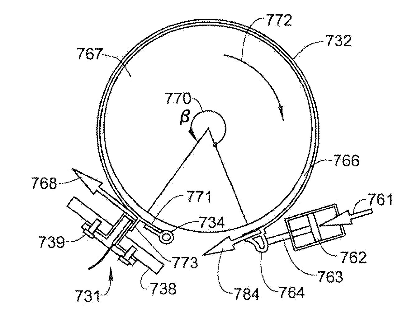
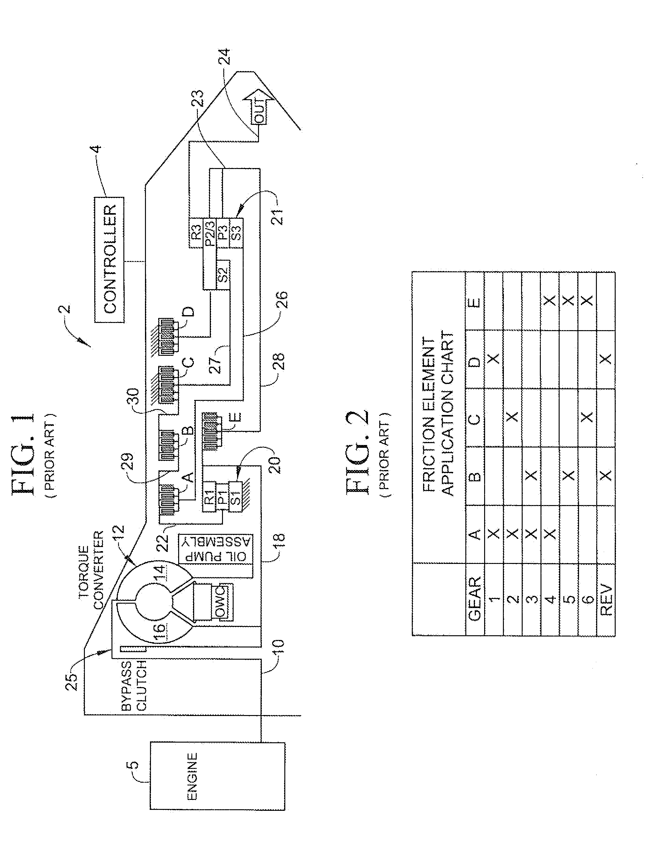
[0057]With initial reference to FIG. 8, there is shown an automotive transmission employing the invention. As this automatic transmission arrangement is similar to the one schematically illustrated in FIG. 1 all the same parts have been indicated with corresponding reference numbers and therefore a duplicate discussion of these parts will not be made here. Instead, of particular importance is the addition of a torque sensor 120 located in friction element C, a load sensor 130 located in friction element D, and a torque sensor 131 located in transmission output shaft 24, all connected to controller 4 for controlling various functions of transmission 2 as will be more fully discussed below.

[0058]FIG. 9 shows a torque phase control method according to a preferred embodiment of the invention for a synchronous friction element-to-friction element upshift from a low gear configuration to a high gear configuration for the automatic transmission system in FIG. 8. The on-coming friction elem...


PUM


Abstract

A closed loop shift control apparatus and method based on friction element load controls a torque transfer phase when shifting from a low gear configuration to a high gear configuration for an automatic transmission system. When pressure actuated friction elements are selectively engaged and released to establish torque flow paths in the transmission, measurements or estimates of torsional load exerted on the off-going friction element are used to predict the optimal off-going friction element release timing for achieving a consistent shift feel. The ideal timing to release the off-going friction element is uniquely defined when torque load exerted onto the off-going friction element becomes substantially zero. An on-coming clutch engagement process is controlled by a closed loop control based on measurements or estimates of on-coming clutch torque capacity for a constant shift feel under dynamically changing conditions.

Description

FIELD OF INVENTION[0001]The present invention pertains to the field of automatic transmissions for motor vehicles and, more particularly, to a shift control apparatus and method based on friction element load level.BACKGROUND OF THE INVENTION[0002]A step-ratio automatic transmission system in a vehicle utilizes multiple friction elements for automatic gear ratio shifting. Broadly speaking, these friction elements may be described as torque establishing elements although more commonly they are referred to as clutches or brakes. The friction elements function to establish power flow paths from an internal combustion engine to vehicle traction wheels. During acceleration of the vehicle, the overall speed ratio, which is the ratio of a transmission input shaft speed to a transmission output shaft speed, is reduced during a ratio upshift as vehicle speed increases for a given engine throttle setting. A downshift to achieve a higher speed ratio occurs as an engine throttle setting increas...

Claims


Application Information

Patent Timeline
Patent Type & Authority Applications(United States)
IPC IPC(8): F16H59/14G06F19/00
CPCF16H61/061F16H2342/044F16H61/686F16H61/08
Inventor FUJII, YUJIPIETRON, GREGORY MICHAELLEE, SEUNG-HOONMCCALLUM, JAMES WILLIAM LOCHREDISSI, MOHAMEDPOPEJOY, DAVIDBUTWIN, JOHNBURKHART, ROBERT ORLEYYANAKIEV, DIANA
Owner FORD GLOBAL TECH LLC
Why Eureka
Try Eureka