Tube for DNA reactions

a technology of reaction tubes and tubes, applied in the field of reaction tubes, can solve the problems of ineffective attempts, inability to completely solve, and require extra electronics and components, and achieve the effect of reducing the evaporation of biological fluid

Active Publication Date: 2010-10-21
GENOMADIX INC
View PDF29 Cites 17 Cited by
  • Summary
  • Abstract
  • Description
  • Claims
  • Application Information

AI Technical Summary

Benefits of technology

[0015]An object of one aspect of the present invention is to minimize e

Problems solved by technology

These attempted solutions were not completely effective since, by definition, the use of a heated lid required extra electronics and components compared to a system without a heated lid.
This attempted solution was not completely effective since mineral oil represents an extra

Method used


Image

  • Tube for DNA reactions
  • Tube for DNA reactions

Examples


Embodiment Construction

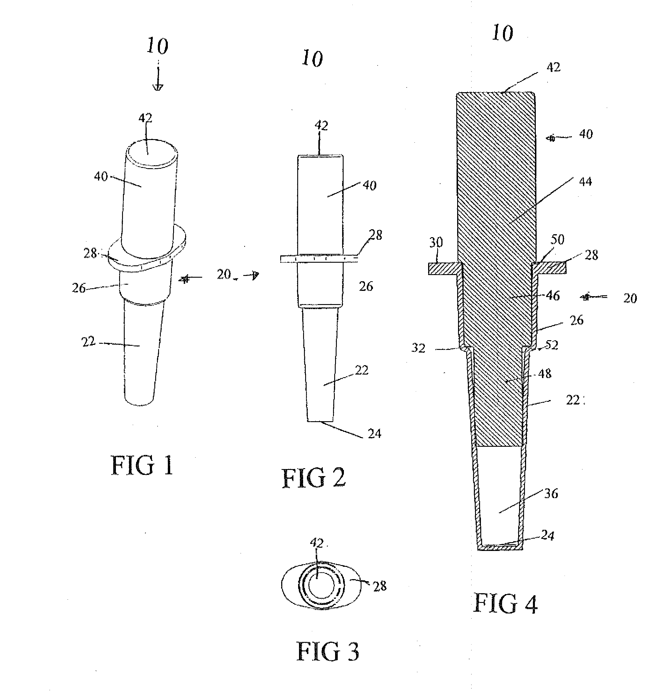
Description of FIG. 1, FIG. 2 and FIG. 3

[0033]As seen in FIG. 1, FIG. 2 and FIG. 3, the reaction tube for use in performing the Polymerase Chain Reaction (PCR) in a thermal cycler, indicated by general numeral 10, which is the subject of the present invention includes a reaction tube 20 which consists of a lower frustoconical portion 22 terminating in a flat bottom 24, a cylindrical upper portion 26 and an upper oval lip 28. The reaction tube for use in performing the Polymerase Chain Reaction (PCR) in a thermal cycler, which is indicated by general numeral 10, is shown sealed by a cap 40 which includes a flat upper end 42.

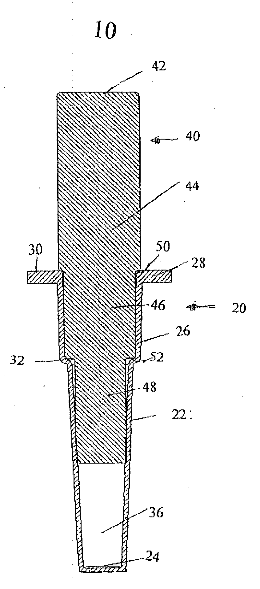
Description of FIG. 4

[0034]As seen in FIG. 4, the reaction tube for use in performing the Polymerase Chain Reaction (PCR) in a thermal cycler, which is indicated by general numeral 10, which is the subject of the present invention includes a reaction tube 20 which, as previously described, consists of a lower frustoconical portion 22 terminating in a flat bottom 2...


PUM

PropertyMeasurementUnit
Angleaaaaaaaaaa
Diameteraaaaaaaaaa
Volumeaaaaaaaaaa

Abstract

A reaction tube for use in performing the Polymerase Chain Reaction (PCR) in a thermal cycler, is provided herein such reaction tube includes a hollow tube of heat conducting synthetic plastics material having an open top and a flat bottom formed of an optically-clear material. Such reaction tube also includes a solid plug cap nesting within said hollow tube and to provide a minimized void volume within the hollow tube and to minimize evaporation and condensation of the biological fluid.

Description

BACKGROUND OF THE INVENTION[0001]1. Field of the Invention[0002]This invention relates to reaction tubes which are used in performing the Polymerase Chain Reaction (PCR) in thermal cyclers utilizing temperature-controlled heat blocks for heating and cooling.[0003]2. Description of the Prior Art[0004]Thin-walled.0.2 mL polypropylene reaction tubes are the standard for performing the Polymerase Chain Reaction (PCR) in thermal cyclers utilizing temperature-controlled heat blocks for heating and cooling, as disclosed, for example, in U.S. Pat. No. 3,725,010 patented Apr. 3, 1973 by Beckman instruments Inc. Typically, the reaction tube is inserted into a well in the heat block so that the sides are surrounded by the heat block but the cap is not in contact with the heat block. Since the cap is not in contact with the heat block, it is cooler than the sides of the tube. There are a number of solutions that have been invented to minimize evaporation and condensation of liquid reagents into...

Claims


Application Information

Patent Timeline
IPC IPC(8): B65D43/04
CPCC12Q1/686C12Q2565/631
Inventor HARDER, CHRISCLOAKE, MARTINPERREAULT, MICHAELLEM, PAULSHAYANPOUR, ALAN
Owner GENOMADIX INC
Why Eureka
Try Eureka