Portal access control system

a technology for controlling access and control systems, applied in transmission systems, alarms, transmissions, etc., can solve the problems of inability to determine the position of cars or persons in queues, inability to determine the intent of users, and inability to distinguish order in queues, etc., to achieve easy differentiation of order in queues, enhance and simplify security

Inactive Publication Date: 2010-10-21
KEYLESS TECH
View PDF9 Cites 65 Cited by
  • Summary
  • Abstract
  • Description
  • Claims
  • Application Information

AI Technical Summary

Benefits of technology

[0027]The Cluster Unit carried by the operator offers a novel system of cluster identification. Enhancing and simplifying security, by enabling the addressing of: Carrier ID together with a group of operators and their ID, as an associated cluster. The system of this invention does not suffer from any of the problems produced by reflections because the signal strength in this invention is kept to a minimum (eg indoors the range will be max @ ˜1.5 meters), negating reflections. The system of this invention is a micro processor controlled field ranging and attenuation system well suited for building interiors (ie a surgeon with sterilized hands walking into a secure room will not have to touch the door and yet pass with security). Through a series of events occurring between a control (base) unit and a carrier, the system of this invention places restraints on the specific variance, either synchronously or independently, of the antenna transmission and reception areas of the said control (base) unit and carrier, so that the simple occurrence of successful communication will indicate the position of the carrier.
[0028]The system of this invention easily distinguishes order in a queue so that it can intuitively open boom gates. The system is keyless and requires no actuation by the vehicle operator or person approaching the door.
[0035]Applied digital variance of the interactive antenna transmissive (Tx) and receptive (Rx) areas, dynamically alters the workable communication area between two transceivers. By minimizing the communication area, the proximity and therefore position of the condition unit relative to the control unit can be deduced, outwardly appearing as a decoding of the intent of the carrier / operator. This system can be implemented as a Rf ranging ID entry system, for commercial, non-commercial and personal use.
[0047]This system can also be easily implemented in other fields of use such as a contact-less RFID entry system, for commercial, non-commercial and personal use.
[0062]The remote unit may be optionally paired with a hidden (within the same vehicle) proximity unit and on loss of encrypted communication with this unit, will auto delete its entire memory. This is to prevent a stolen remote unit being used to illegally access a portal.

Problems solved by technology

Automatic door opening systems are usually indiscriminate and open when a person or vehicle enters near the range of the proximity sensor.
RFID (Radio Frequency Identification Device) tags can provide information about the identity of the RFID carrier but there is no means for determining the intent of the user.
This system is unable to determine the position of cars or persons in a queue and is limited to handshaking with one remote unit per portal pass.
Further this system is unable to operate within a building because of the serious reflections produced by:1) the base station antenna power and walls will reflecting the signals2) standing waves set up in the building by the base station antenna will produce null zones (no signal)3) the signal strength has the potential to penetrate floors and interfere with other remote and base station devices.

Method used


Image

  • Portal access control system
  • Portal access control system
  • Portal access control system

Examples


Embodiment Construction

[0170]A number of embodiments of the invention will be described with reference to the drawings in which:

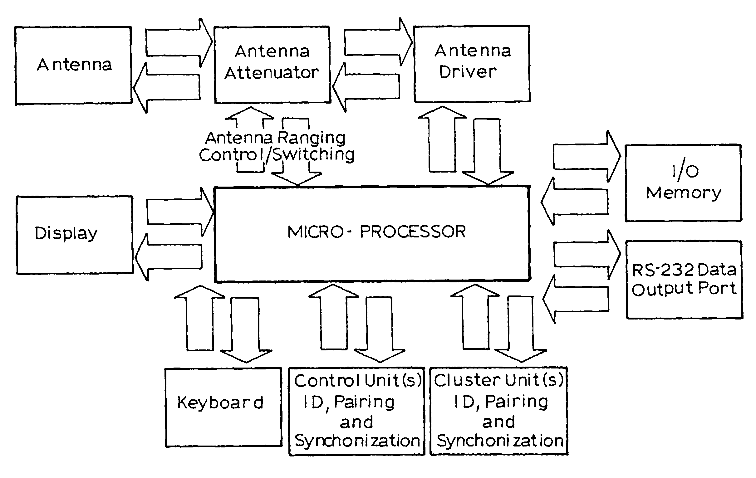
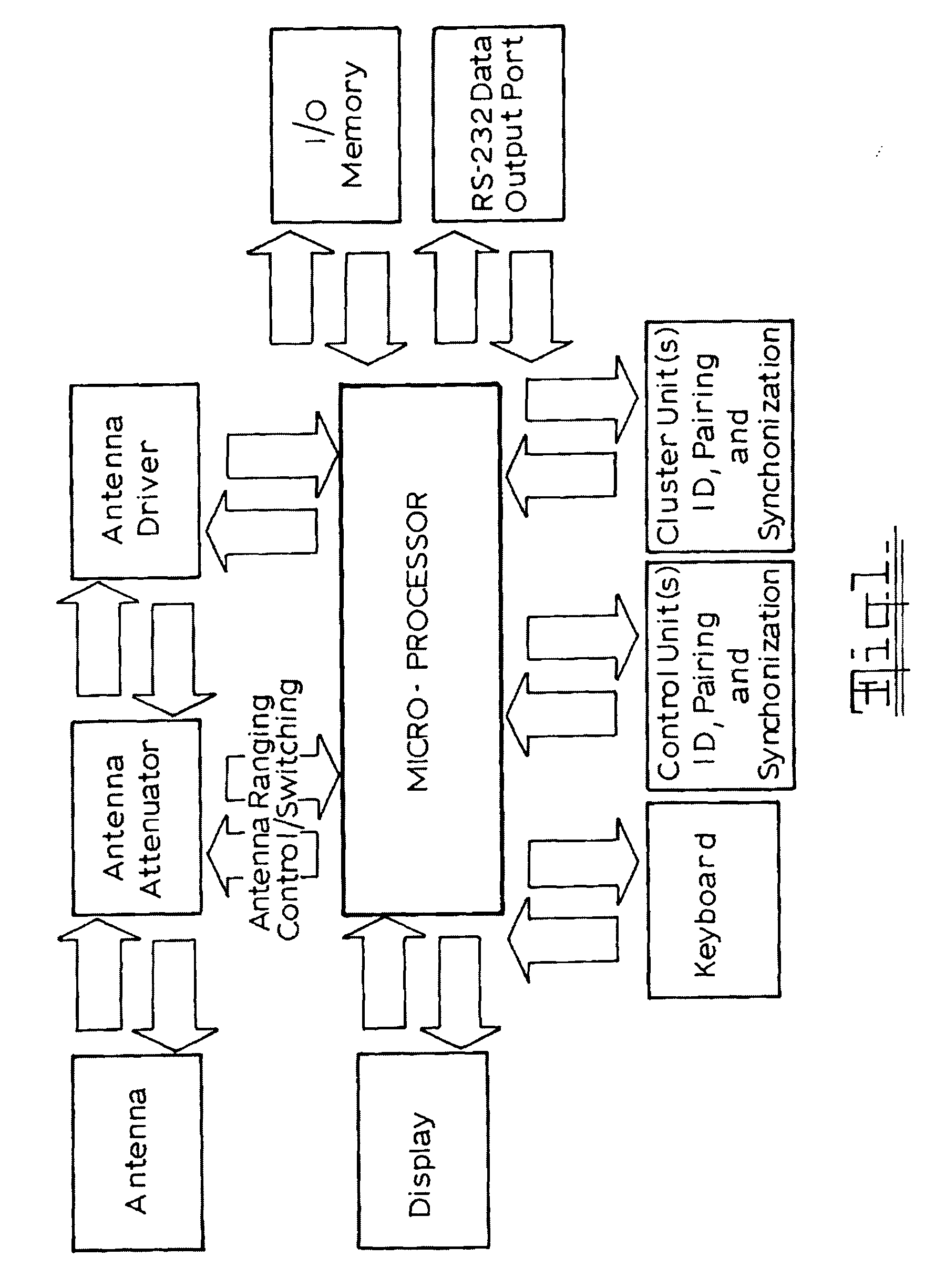
[0171]FIG. 1 illustrates a block diagram of the major components of the Control Unit;

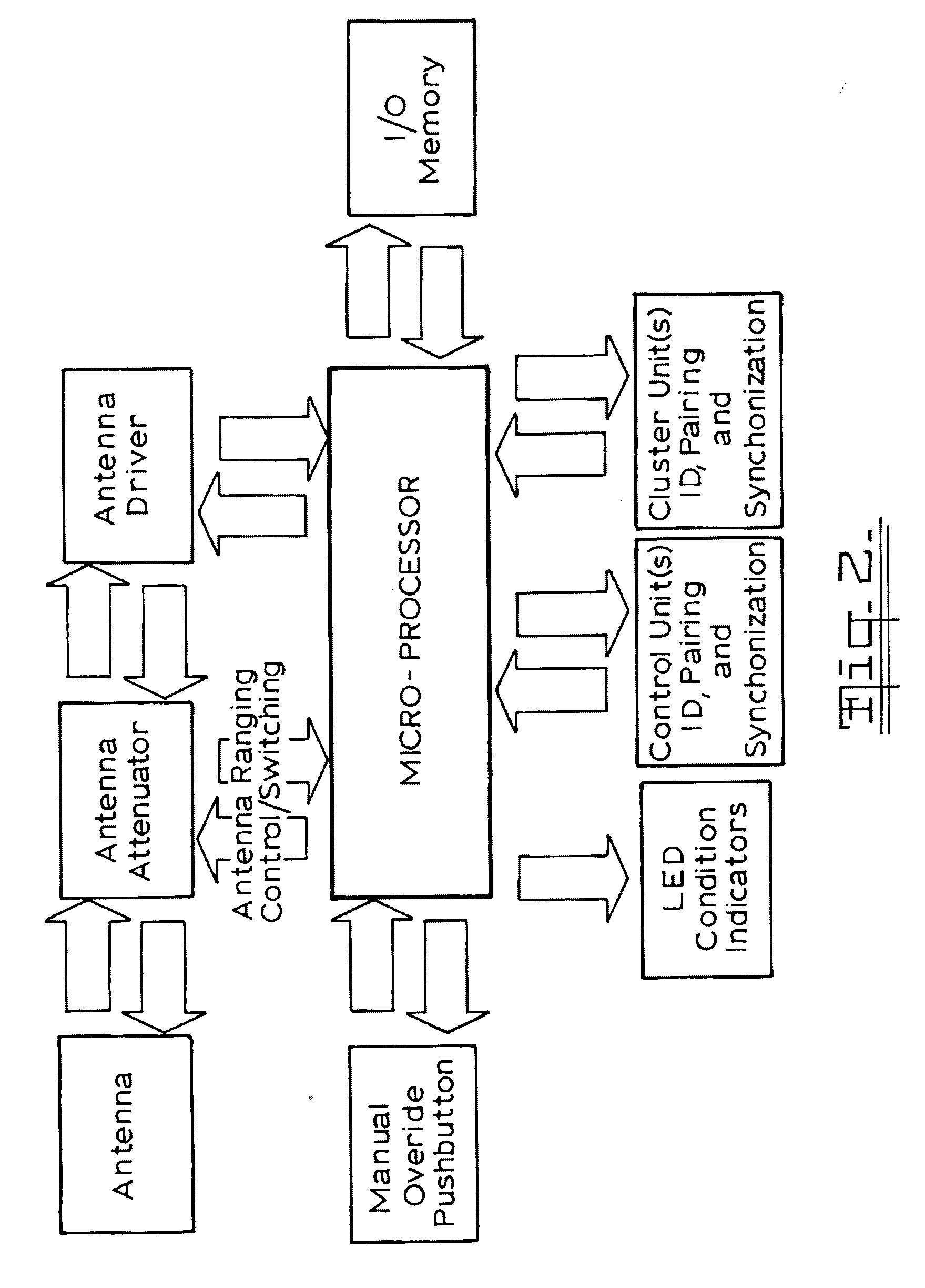
[0172]FIG. 2 illustrates a block diagram of the major components of the Condition unit;

[0173]FIG. 3 illustrates an even (normal) pattern of communication between two antennas and their transmitting (Tx) and reception (Rx) fields.

[0174]FIG. 4 illustrates an uneven radiation pattern where the transmitting field radiates with much less power than the receptive field. The antennas illustrated will not communicate properly.

[0175]FIG. 5 illustrates the position where the uneven radiation pattern fields of antennas of FIG. 4 will communicate.

[0176]FIG. 6 illustrates the Rf radiation field patterns of the Control Unit with unattenuated radiation patterns and a Condition unit placed in a vehicle approaching a garage with unattenuated radiation patterns;

[0177]FIG. 7 illustrates the Rf radiation field patte...


PUM


Abstract

A combination of specific antenna type(s), with a system of specific antenna Rf field deployment, combined with the intelligent sensing of differing micro processor control of a digital antenna attenuator that controls disproportional attenuation (either synchronously or independently) of the transmission and reception areas of the antenna(e), of electronically paired devices, together with conditional time delays, is used to securely determine the ID and intent of an Rf access system user. A multifunctional remote device (condition unit) is carried by a carrier, the remote device transmits a short range radio frequency (Rf) signal which, when within range, is received by a stationary control unit. A second multifunctional remote device (cluster unit) is carried by the operator of the carrier and must be in secure communication with the condition unit to enable secure transmission between the control and the control unit. The operation of both said multifunctional remote units changes significantly with application in differing fields of use. By intelligently varying the interactive antenna Tx and Rx area, the proximity and therefore position of the remote (condition) unit to the base (control) unit can be deduced, outwardly appearing as a decoding of the intent of the carrier. This system can be implemented as a secure card-less RFID entry system for vehicle, building, border entry and mass transit systems.

Description

[0001]This invention relates to an automatic access system which does not require any initiation by the person or vehicle approaching a portal such as a door or barrier.BACKGROUND TO THE INVENTION[0002]Most portal / access opening systems for vehicles or persons require the user to:[0003]Swipe a proximity card,[0004]Force the user to:[0005]1) Carry a specific smart entry and RFID device;[0006]2) Pass through a portal where the electronic interrogation can occur (ie: eTag);[0007]Push a button on a smart entry device (ie: a key fob)[0008]Use electronic biometric scanning applied to parts of the physical body, or[0009]Enter a code that actuates the door or barrier to open.[0010]RFID (Radio Frequency Identification Device) tags and devices can provide information about the identity of the RFID carrier. For example: RFID Tags and RFID Contact-less Smart Cards.[0011]Automatic door opening systems are usually indiscriminate and open when a person or vehicle enters near the range of the proxi...

Claims


Application Information

Patent Timeline
Patent Type & Authority Applications(United States)
IPC IPC(8): G06F7/04
CPCB60R25/245E05Y2400/82G07C9/00111G07C9/02E05F15/73H01Q1/3241E05F15/00E05Y2900/106G07C2009/00928G07C9/10G07C9/28
Inventor CAP, GEORGE JAROSLAVWOODFIELD, ROSSGOURDREAS, LEON
Owner KEYLESS TECH
Why Eureka
Try Eureka