Exhaust purification device for hybrid electric vehicle

a hybrid electric vehicle and purification device technology, applied in the direction of air quality improvement, special data processing applications, driver input parameters, etc., can solve the problems of urea in the injected urea water not being satisfactorily hydrolyzed within the exhaust gas, exhaust gas cannot be purified, urea slippage, etc., to increase the amount of ammonia adsorption, reduce the occurrence of ammonia slippage, and prevent the effect of ammonia slippag

Inactive Publication Date: 2010-10-21
MITSUBISHI FUSO TRUCK AND BUS CORPORATION
View PDF7 Cites 32 Cited by
  • Summary
  • Abstract
  • Description
  • Claims
  • Application Information

AI Technical Summary

Benefits of technology

[0028]In this case, the exhaust temperature can be gradually raised so that the maximum ammonia adsorption amount may decrease with increase in the temperature of the ammonia selective reduction-type NOx catalyst, without dropping below the amount of ammonia actually adsorbed by the ammonia selective reduction-type NOx catalyst and consumed by the selective reduction of NOx. It is therefore possible to reliably prevent the occurrence of ammonia slip at the start of the engine. Also, in this case, since the elevation of the exhaust temperature need not be delayed more than necessary, the exhaust temperature can be raised as quickly as possible to the temperature at which the urea water can be supplied.
[0029]Further, also in the case where the exhaust purification device is configured such that after the engine is started, the control unit causes the control amount of the engine to gradually approach the...

Problems solved by technology

However, the exhaust gas from the engine still contains pollutants, and therefore, an exhaust purification device is used to purify the exhaust gas.
In the case of such an exhaust purification device provided with the ammonia selective reduction-type NOx catalyst, immediately after the engine is started, the temperature of the ammonia selective reduction-type NOx catalyst and of the urea-water injector is low, and thus the urea in the injected urea water cannot be satisfactorily hydrolyzed within the exhaust gas.
However, if the supply of the urea water is stopped after the sta...

Method used


Image

  • Exhaust purification device for hybrid electric vehicle
  • Exhaust purification device for hybrid electric vehicle
  • Exhaust purification device for hybrid electric vehicle

Examples


first embodiment

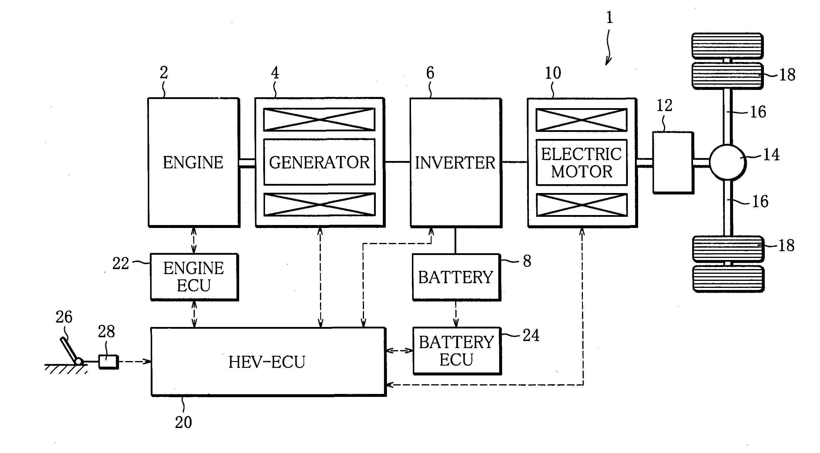
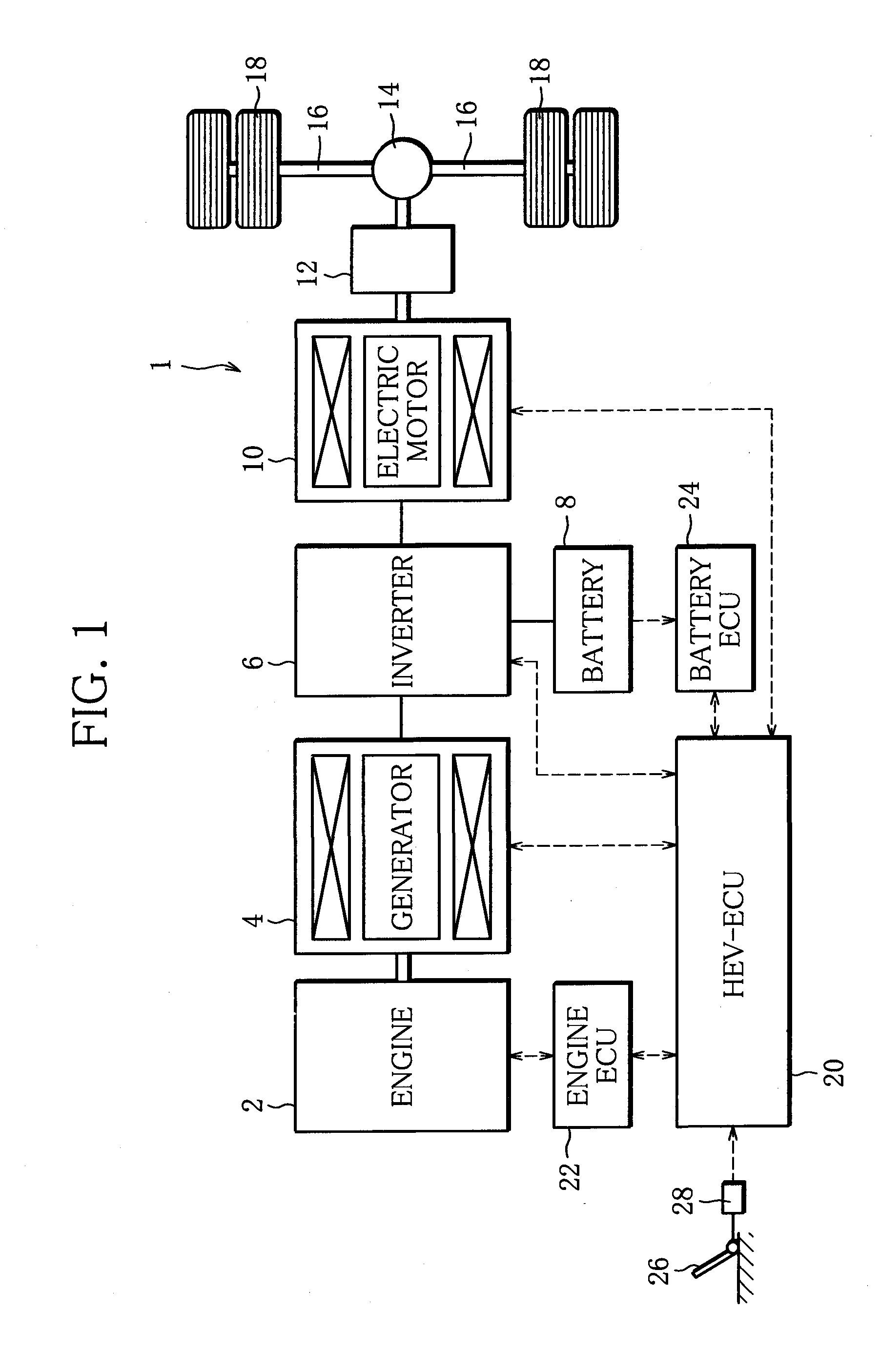
[0041]FIG. 1 illustrates an entire configuration of a series-type hybrid electric vehicle 1 to which is applied an exhaust purification device according to the present invention.

[0042]A diesel engine (hereinafter, merely referred to as engine) 2 has an output shaft coupled to a rotary shaft of a generator 4. The output of the engine 2 is not used for moving the vehicle but is used to drive the generator 4. Electric power generated by the generator 4 as it is driven by the engine 2 is stored in a battery 8 through an inverter 6. The inverter 6 controls the electric current flowing between the generator 4 and the battery 8 to adjust the electric power to be generated by the generator 4 so that the battery 8 may be properly charged with the electric power supplied from the generator 4. Also, the generator 4 can be supplied with electric power from the battery 8 while the engine 2 is stopped, whereupon the generator 4 functions as an electric motor to crank the engine 2.

[0043]The hybrid...

second embodiment

[0163]Also in the second embodiment, the engine operation control is started when the starting switch is operated to the ON-position, as in the charge control. Following the procedure illustrated in the flowchart of FIG. 8, the HEV-ECU 20 executes the engine operation control at the predetermined control intervals in parallel with the charge control. Further, the engine operation control is terminated when the starting switch is operated to the OFF-position, as in the charge control.

[0164]In the engine operation control, the HEV-ECU 20 instructs the engine ECU 22 to start and stop the operation of the engine 2 and also to switch the operation mode during the operation of the engine 2 in accordance with the values of the flags F1 and F2 set by the charge control. Following the instructions, the engine ECU 22 starts or stops the operation of the engine 2 and switches the operation mode.

[0165]When the starting switch is operated to the ON-position and thus the engine operation control ...


PUM

PropertyMeasurementUnit
Temperatureaaaaaaaaaa
Poweraaaaaaaaaa
Speedaaaaaaaaaa

Abstract

An ammonia selective reduction-type NOx catalyst (48) is interposed in an exhaust passage of an engine (2) provided in a series-type hybrid electric vehicle (1), and a urea water injector (52) is disposed in the exhaust passage to supply a urea water into exhaust gas existing upstream of the ammonia selective reduction-type NOx catalyst (48). The engine (2) is started and stopped in accordance with the storage state of a battery (8), and the urea water injector (52) is controlled in accordance with the operating state of the engine (2). When the engine (2) is to be stopped, an adsorption increasing operation for increasing the amount of ammonia adsorbed by the ammonia selective reduction-type NOx catalyst (48) is executed over a predetermined period before the engine (2) is stopped.

Description

TECHNICAL FIELD[0001]The present invention relates to an exhaust purification device for use in a hybrid electric vehicle. More particularly, the invention relates to an exhaust purification device for a series-type hybrid electric vehicle wherein a generator is driven by using power from an engine which is not used for moving the vehicle, the electric power generated by the generator is stored in a battery, and an electric motor is driven by the electric power supplied from the battery and used as a power source for moving the vehicle.BACKGROUND ART[0002]A type of hybrid electric vehicle known as a series-type hybrid electric vehicle has been developed and put to practical use, in which a generator is driven by the power of an engine which is not used for moving the vehicle, the electric power generated by the generator is stored in a battery, and an electric motor is driven by the electric power supplied from the battery and used as a power source for moving the vehicle. In such a...

Claims


Application Information

Patent Timeline
IPC IPC(8): F02D43/00F01N3/10B60L50/15
CPCB60W2510/0638F01N13/009B60W2510/068B60W2510/0685B60W2510/244B60W2520/10B60W2540/10B60W2710/0644F01N3/035F01N3/106F01N3/208F01N2560/06F01N2590/11F01N2610/02F01N2900/1622F02D29/02F02D41/0235F02D41/042F02D2041/1469F02N11/0818F02N2200/061Y02T10/54Y02T10/6217Y02T10/6286Y02T10/7005Y02T10/7044Y02T10/705Y02T10/7077B01D53/9418B01D53/9459B01D53/9477B01D53/9495B01D2251/2067B01D2258/012B60K1/02B60K6/46B60L11/123B60L11/1861B60L2240/441B60L2240/445B60W10/06B60W10/08B60W20/00B60W2510/0604Y02T10/24F01N13/0097B60W2510/0676F02N11/0829B60L50/61B60L58/12Y02A50/20Y02T10/12Y02T10/40Y02T10/62Y02T10/70B60K2006/268B60W20/15Y02T10/7072
Inventor HIRANUMA, SATOSHIMURATA, MINEHIROTAKEDA, YOSHINAKAFUJITA, HIROAKIHORII, YUSUKE
Owner MITSUBISHI FUSO TRUCK AND BUS CORPORATION
Why Eureka
Try Eureka