Method and apparatus for controlling ion energy distribution

a technology of ion energy distribution and control method, which is applied in the field of plasma processing, can solve the problems of ineffective voltage placement of voltage across the surface of the substrate, limiting the ability of the plasma process to carry out the desired etching profile, and expensive techniques to achieve narrow ion energy distribution

Active Publication Date: 2010-11-04
AES GLOBAL HLDG PTE LTD
View PDF67 Cites 72 Cited by
  • Summary
  • Abstract
  • Description
  • Claims
  • Application Information

AI Technical Summary

Benefits of technology

[0005]Illustrative embodiments of the present invention that are shown in the drawings are summarized below. These and other embodiments are more fully described in the Detailed Description section. It is to be understood, however, that there is no intention to limit the invention to the forms described in this Summary of the Invention or in the Detailed Description. One skilled in the art can recognize that there are numerous modifications, equivalents, and alternative constructions that fall within the spirit and scope of the invention as expressed in the claims.

Problems solved by technology

If the substrate is a dielectric, however, a non-varying voltage is ineffective to place a voltage across the surface of the substrate.
In many instances, it is desirable to have a narrow ion energy distribution, but applying a sinusoidal waveform to the substrate induces a broad distribution of ion energies, which limits the ability of the plasma process to carry out a desired etch profile.
Known techniques to achieve a narrow ion energy distribution are expensive, inefficient, difficult to control, and may adversely affect the plasma density.
As a consequence, these known techniques have not been commercially adopted.

Method used


Image

  • Method and apparatus for controlling ion energy distribution
  • Method and apparatus for controlling ion energy distribution
  • Method and apparatus for controlling ion energy distribution

Examples


Embodiment Construction

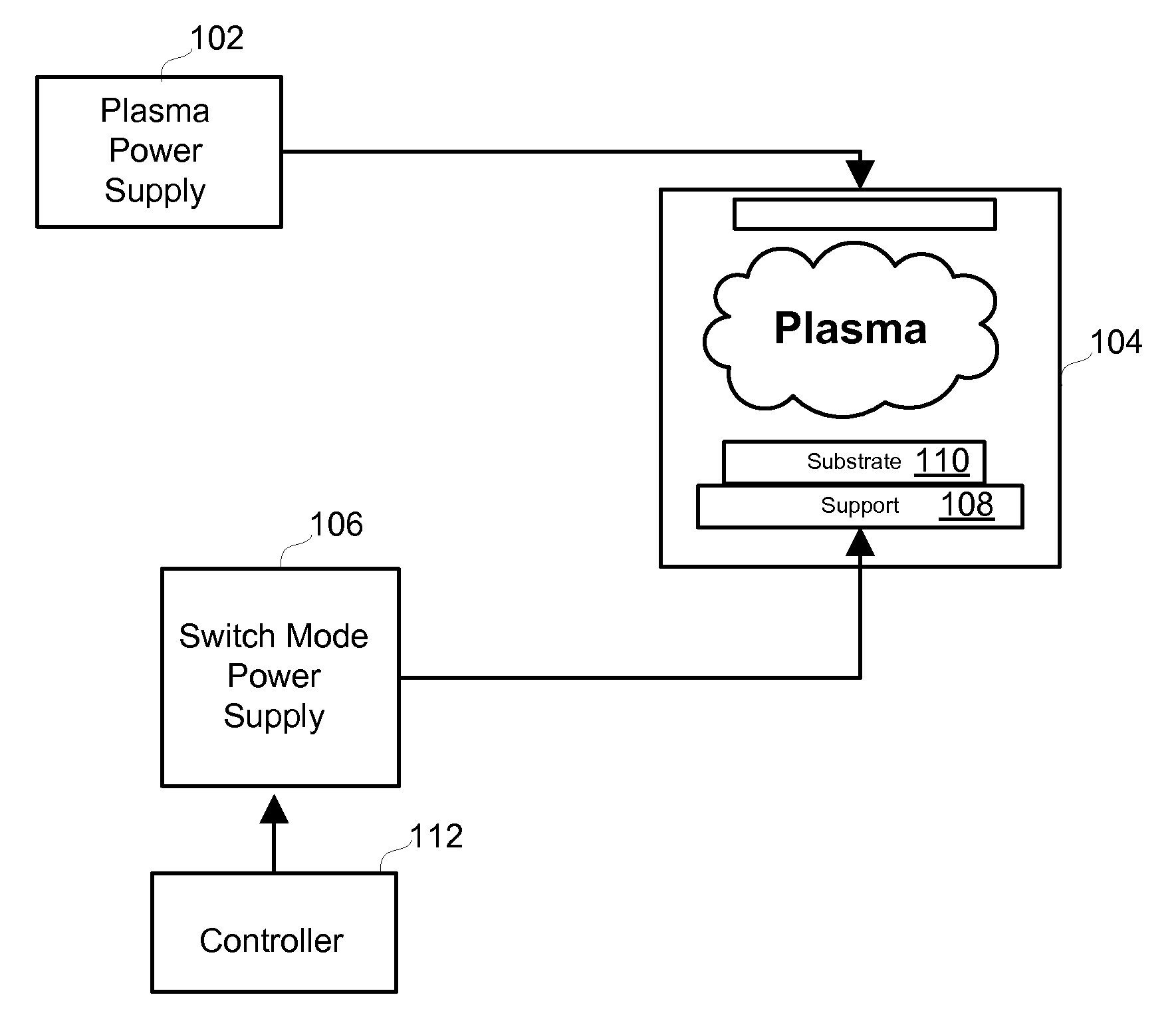
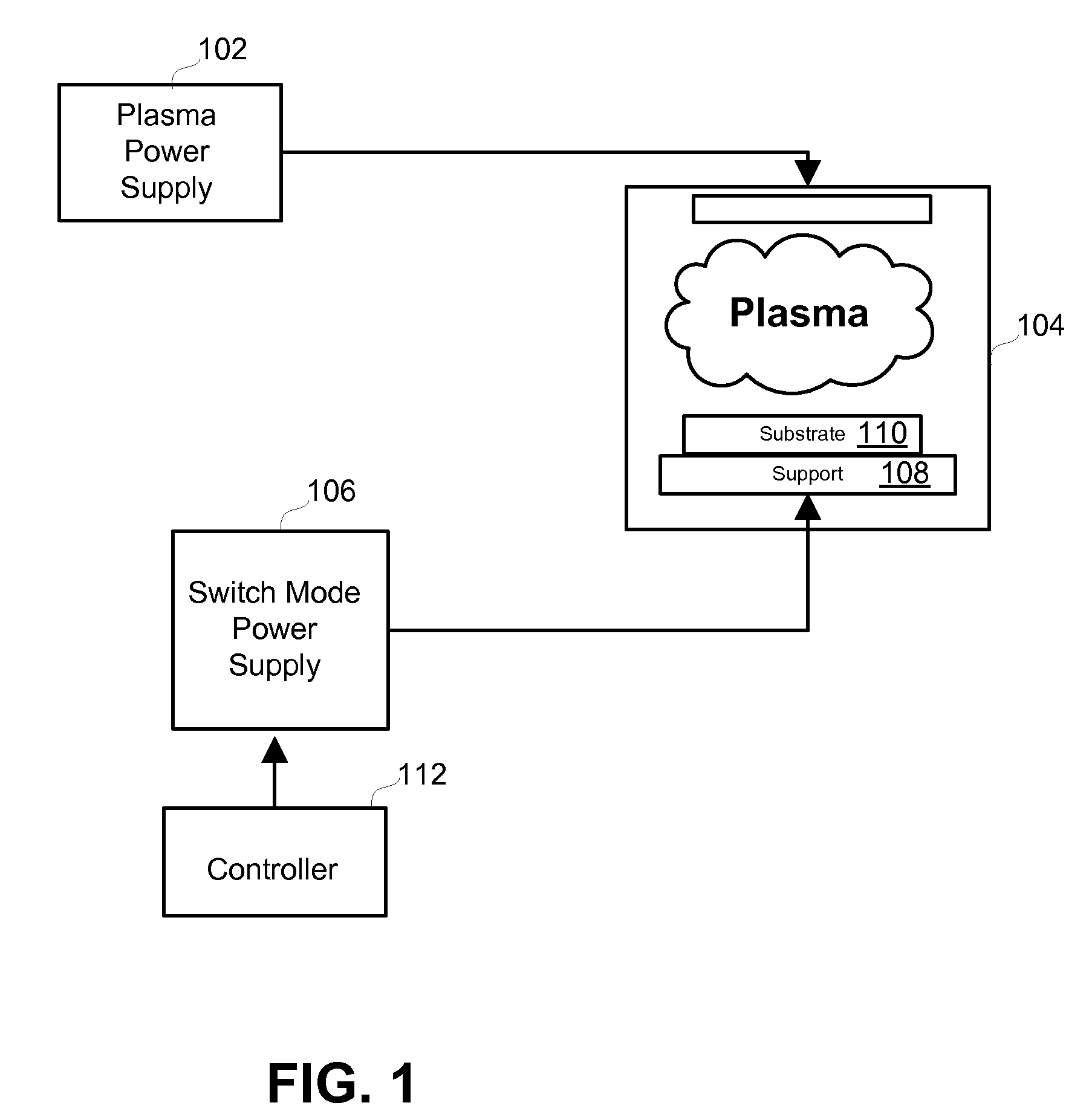
[0017]An exemplary embodiment of a plasma processing system is shown generally in FIG. 1. As depicted, a plasma power supply 102 is coupled to a plasma processing chamber 104 and a switch-mode power supply 106 is coupled to a support 108 upon which a substrate 110 rests within the chamber 104. Also shown is a controller 112 that is coupled to the switch-mode power supply 106.

[0018]In this exemplary embodiment, the plasma processing chamber 104 may be realized by chambers of substantially conventional construction (e.g., including a vacuum enclosure which is evacuated by a pump or pumps (not shown)). And, as one of ordinary skill in the art will appreciate, the plasma excitation in the chamber 104 may be by any one of a variety of sources including, for example, a helicon type plasma source, which includes magnetic coil and antenna to ignite and sustain a plasma 114 in the reactor, and a gas inlet may be provided for introduction of a gas into the chamber 104.

[0019]As depicted, the e...


PUM

PropertyMeasurementUnit
frequenciesaaaaaaaaaa
ion-energyaaaaaaaaaa

Abstract

Systems, methods and apparatus for regulating ion energies in a plasma chamber are disclosed. An exemplary system includes an ion-energy control portion, and the ion-energy control portion provides at least one ion-energy control signal responsive to at least one ion-energy setting that is indicative of a desired distribution of energies of ions bombarding a surface of a substrate. A controller is coupled to the switch-mode power supply, and the controller provides at least two drive-control signals. In addition, a switch-mode power supply is coupled to the substrate support, the ion-energy control portion and the controller. The switch-mode power supply includes switching components configured to apply power to the substrate responsive to the drive signals and the ion-energy control signal so as to effectuate the desired distribution of the energies of ions bombarding the surface of the substrate.

Description

FIELD OF THE INVENTION[0001]The present invention relates generally to plasma processing. In particular, but not by way of limitation, the present invention relates to methods and apparatuses for plasma-assisted etching and / or deposition.BACKGROUND OF THE INVENTION[0002]Many types of semiconductor devices are fabricated using plasma-based etching techniques. If it is a conductor that is etched, a negative voltage with respect to ground may be applied to the conductive substrate so as to create a substantially uniform negative voltage across the surface of the substrate conductor, which attracts positively charged ions toward the conductor, and as a consequence, the positive ions that impact the conductor have substantially the same energy.[0003]If the substrate is a dielectric, however, a non-varying voltage is ineffective to place a voltage across the surface of the substrate. But an AC voltage (e.g., high frequency) may be applied to the conductive plate (or chuck) so that the AC ...

Claims


Application Information

Patent Timeline
Patent Type & Authority Applications(United States)
IPC IPC(8): C23C14/34
CPCC23C14/54H01J37/32009H01J37/3299H01J37/32174H01J37/32935H01J37/32082C23C16/509H02M3/01H02M3/158H02M7/4815H01J37/32944H01J37/32706H01J37/32146H01J37/32577H01J37/32715H01L21/205H01L21/3065H01J37/32045
Inventor HECKMAN, RANDYBROUK, VICTOR
Owner AES GLOBAL HLDG PTE LTD
Why Eureka
Try Eureka