
Scotopically enhanced emergency light and control thereof

a technology of emergency lights and scotopes, applied in emergency power supply arrangements, process and machine control, instruments, etc., can solve the problems of reducing power consumption, reducing visibility, and maintaining constant power levels, so as to reduce the power consumption of emergency lights over tim

Active Publication Date: 2010-11-04
HUBBELL LIGHTING INC
View PDF17 Cites 34 Cited by
  • Summary
  • Abstract
  • Description
  • Claims
  • Application Information

AI Technical Summary

Benefits of technology

[0008]Exemplary embodiments of the present invention address at least the above problems and / or disadvantages and provide at least the advantages described below. Accordingly, an aspect of the present invention is to provide an emergency lighting system and method where power consumption of emergency lights is reduced over time while maintaining scotopically enhanced visibility.
[0011]According to another exemplary implementation of certain embodiments of the present invention, the controller causes the current to the LED to be reduced over a time period when an emergency event is declared.

Problems solved by technology

For emergency lighting conservation of energy becomes even more critical because emergency lighting is often operated using back-up battery power, or other emergency power sources having a limited available power over a given duration of time.
However, the reduction of power must be mitigated by potentially reduced visibility as the light dim in such during emergency lighting application.
On the other hand, while conventional LED-based emergency lighting systems, for example as described in Bolta et al, operate at a reduced power compared to normal lighting conditions, this reduced power is maintained at a constant level not allowing for further power conservation to be achieved.

Method used


Image

  • Scotopically enhanced emergency light and control thereof
  • Scotopically enhanced emergency light and control thereof
  • Scotopically enhanced emergency light and control thereof

Examples


Embodiment Construction

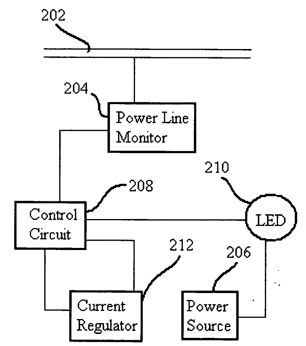
[0022]Referring now to the drawings, wherein like reference numerals designate identical or corresponding parts throughout the several views, embodiments of the present invention are shown in schematic detail.

[0023]The matters defined in the description such as a detailed construction and elements are nothing but the ones provided to assist in a comprehensive understanding of the invention. Accordingly, those of ordinary skill in the art will recognize that various changes and modifications of the embodiments described herein can be made without departing from the scope and spirit of the invention. Also, well-known functions or constructions are omitted for clarity and conciseness.

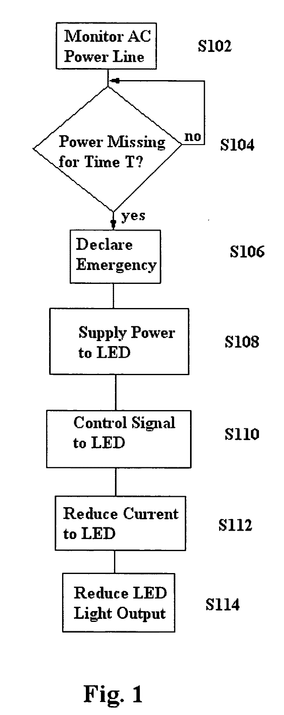
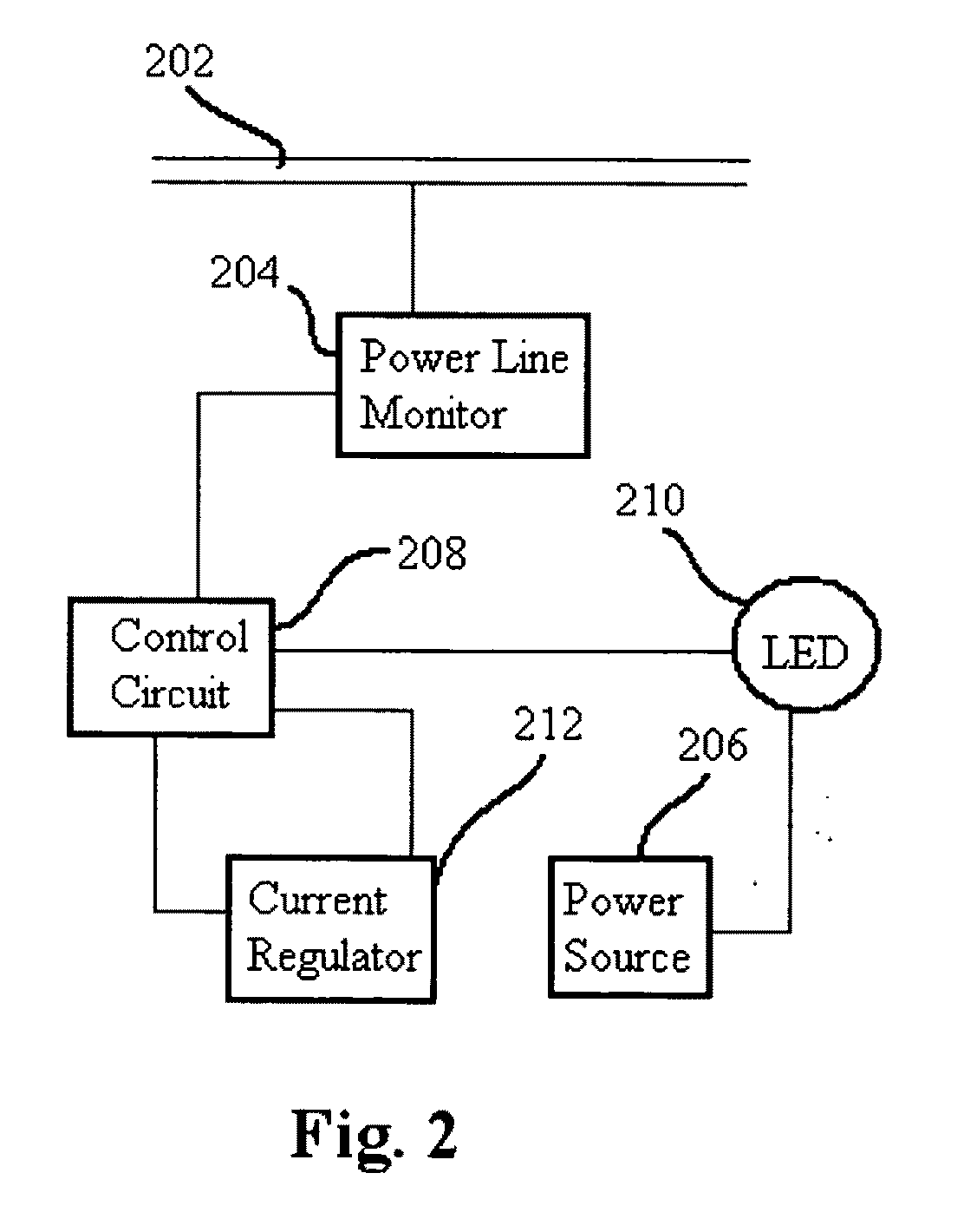
[0024]According to exemplary embodiment of the present invention, a system and method are provided where emergency lighting is activated and powered as explained below with reference to exemplary process flow diagram of FIG. 1.

[0025]As illustrated in the example of FIG. 1, and with reference to FIG. 2, AC ...


PUM


Abstract

System and method are provided for controlling emergency lighting where emergency lights turn on when main source of power goes out for controlling emergency lighting to conserve energy utilized by the emergency light, while maintaining good visibility of the emergency lighting. Solid state lighting, such as LED, is used within an emergency light to add light in blue wavelength region matching the light output to the most sensitive of wavelength response of the human eve to increase color perception and allows faster response time. Electrical current to the device and light output are reduced while LED light tends to increase its blue wavelength component as it is dimmed thus increasing effective light output. After a predetermined time, the light is purposefully dimmed to conserve energy and to allow the eye to slowly and safely adjust to the new lighting conditions. By reducing electrical current, energy storage batteries may be smaller than for similar unit that maintains constant light output.

Description

BACKGROUND OF THE INVENTION[0001]1. Field of the Invention[0002]The present invention generally relates to systems and methods for controlling emergency lighting where emergency lights turn on when main source of power goes out. More particularly, the present invention relates to lighting systems and methods for controlling emergency lighting to conserve energy utilized by the emergency light, while maintaining good visibility of the emergency lighting.[0003]2. Discussion of the Background[0004]An important consideration for emergency lighting is visibility. For example, U.S. Pat. No. 7,234,844 to Bolta et al., the entire disclosure of which is hereby incorporated by reference, describes emergency lighting fixtures that incorporate light emitting diode (LED) lighting sources made with scotopically rich primary colors which increase perceived light even under a low lumen output, because the human eye responds more to blue light and less to yellow / red light. That is, Bolta et al. desc...

Claims


Application Information

Patent Timeline
IPC IPC(8): H01J13/32H05B37/02
CPCH05B33/0854H05B45/10
Inventor BUTTERIS, JAMEY L.HEATON, THOMAS K.STARINKI, MICHAEL A.
Owner HUBBELL LIGHTING INC
Learn More