Method and system for detecting an occupancy state of a vehicle seat

Inactive Publication Date: 2010-11-04
IEE INT ELECTRONICS & ENG SA
View PDF5 Cites 31 Cited by
  • Summary
  • Abstract
  • Description
  • Claims
  • Application Information

AI Technical Summary

Benefits of technology

[0007]The disclosure provides for an improved de

Problems solved by technology

A challenge of capacitive occupant detection systems is reliable detection of a we

Method used


Image

  • Method and system for detecting an occupancy state of a vehicle seat
  • Method and system for detecting an occupancy state of a vehicle seat
  • Method and system for detecting an occupancy state of a vehicle seat

Examples


Example

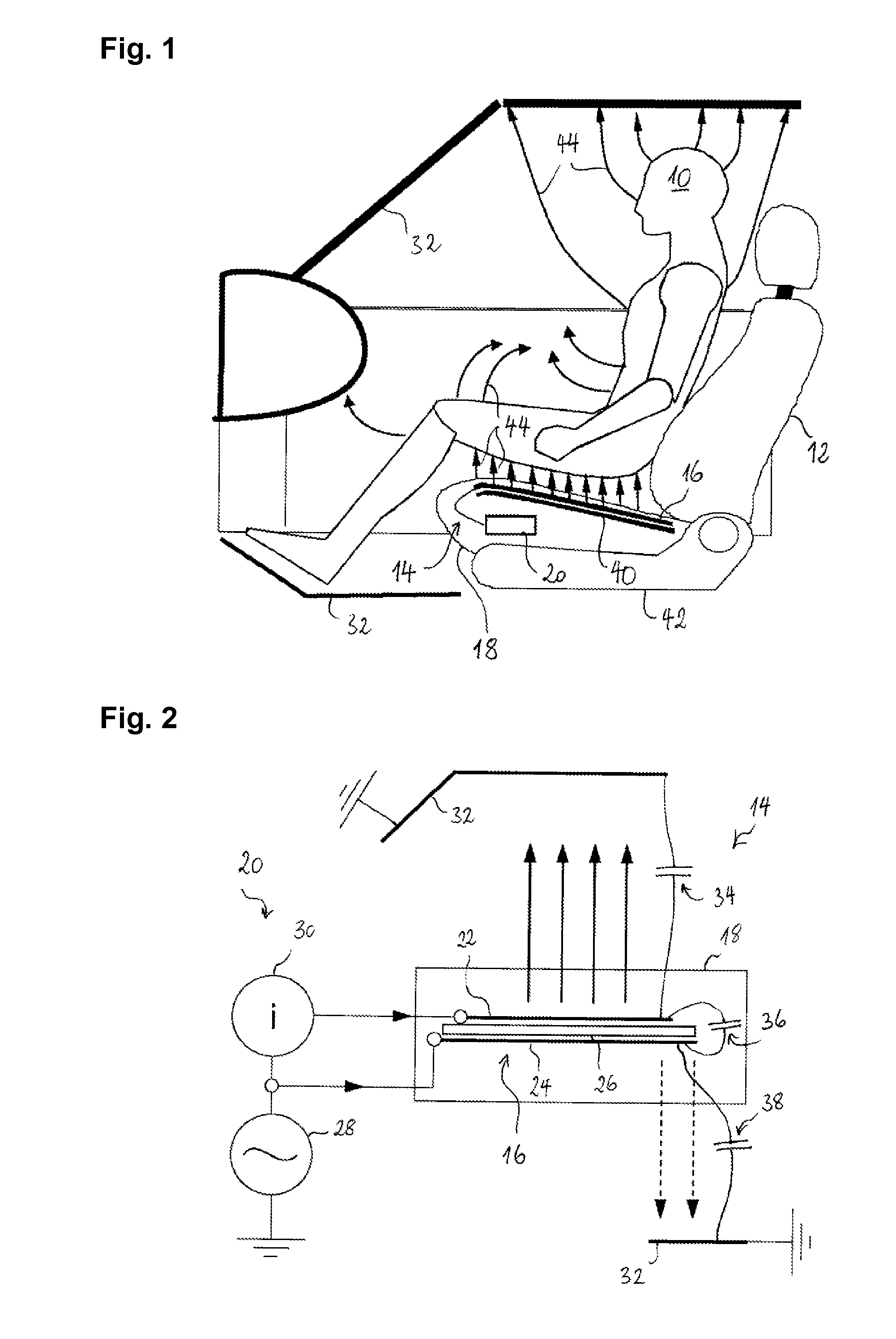
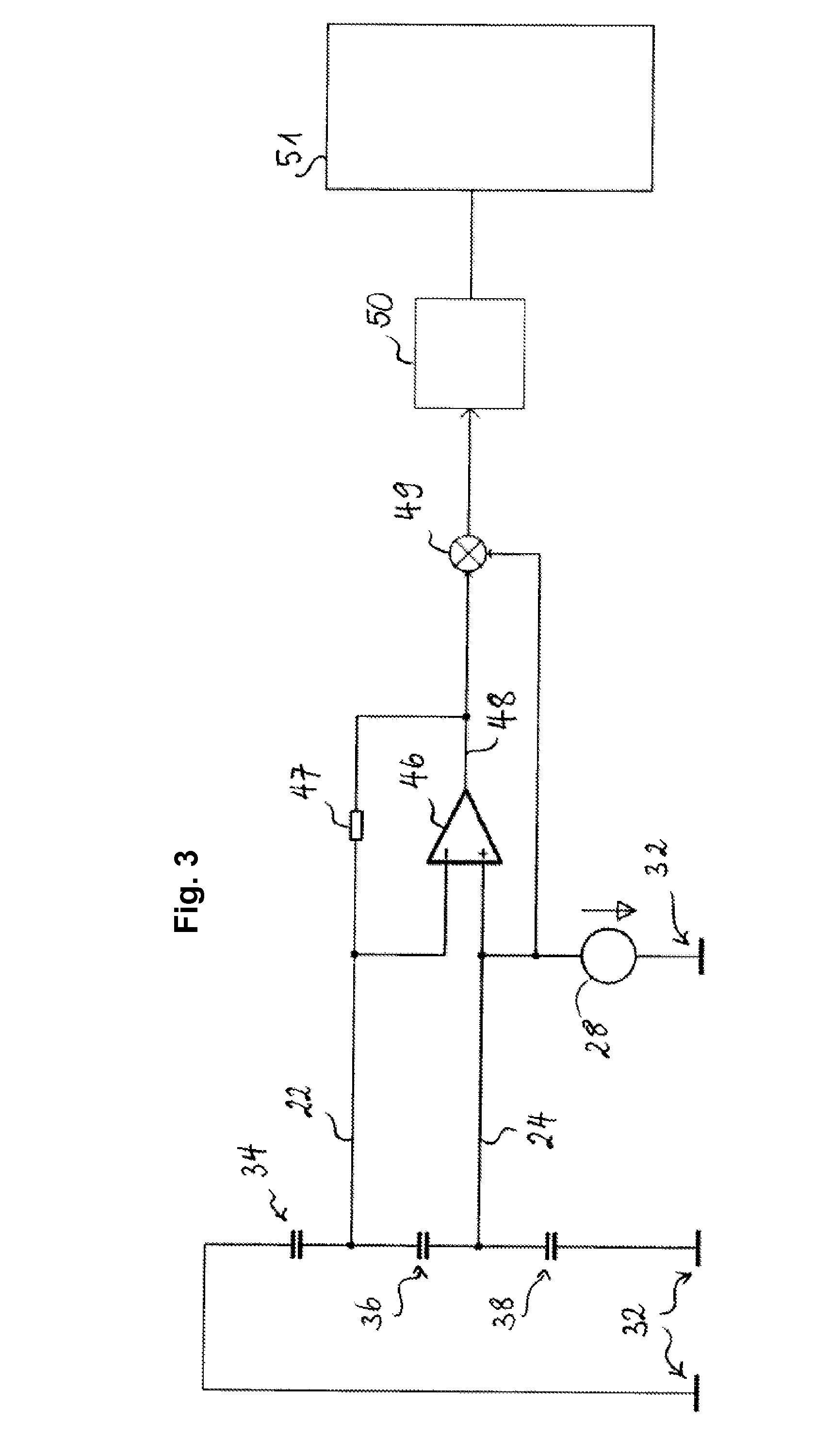
[0029]FIG. 3 shows a (simplified) equivalent circuit diagram of a first embodiment of a capacitive occupant detection system. Oscillator 28 applies an AC voltage to the shield electrode 24. Amplifier 46 and feedback impedance 47 form together a transimpedance amplifier, which maintains the voltage on the antenna electrode 22 substantially equal to the voltage on the shield electrode 24. The transimpedance amplifier thus converts the current flowing into the antenna electrode 22 into a voltage at the amplifier output 48. Since the antenna electrode 22 is at any moment of this measurement at substantially the same potential as the shield electrode 24, the current through the second capacitance 38 remains essentially zero. Therefore, the current flowing into the antenna electrode depends almost exclusively only on the first capacitance 34. Mixer 49 and low pass filter 50 convert the AC output of amplifier 46 to a DC voltage, which is dependent on the first capacitance 34. This voltage ...

Example

[0032]FIG. 5 shows a (simplified) equivalent circuit diagram of a second embodiment of a capacitive occupant detection system. In this embodiment, the electrode arrangement comprises only a single antenna electrode 22 and no shield electrode. Oscillator 28 applies an AC voltage to the non-inverting input of amplifier 46 and feedback impedance 47, forming together a transimpedance amplifier, which maintains the voltage on the antenna electrode 22 substantially equal to the voltage output by the oscillator 28. The transimpedance amplifier thus converts the current flowing into the antenna electrode 22 into a voltage at the amplifier output 48. The current flowing into the antenna electrode 22 depends almost on the capacitance 34 between the antenna electrode and vehicle ground 32. Mixer 49 and low pass filter 50 convert the AC output 48 of amplifier 46 to a DC voltage, which is dependent on the capacitance 34. This voltage is fed to an analog-to-digital converter (ADC) input of a micr...

Example

[0033]FIG. 6 shows a simplified equivalent circuit diagram of a third embodiment of a capacitive occupant detection system. In this embodiment, the occupant detection system comprises a first antenna electrode 22 and a second antenna electrode 122. One of the antenna electrodes 22, 122 is preferably arranged in the seating portion of the vehicle seat, whereas the other may be arranged, for instance, in the seat back, the foot well or the dashboard. The oscillator 28 is operatively connected to the first antenna electrode 22 and applies thereto an oscillating voltage, when the system is operating. The second antenna electrode 122 connected to the inverting input of an amplifier 46, which forms, together with impedance 47, a transimpedance amplifier. The latter amplifies the current flowing in the second antenna electrode in response to an oscillating voltage being applied to the first antenna electrode 22. Mixer 49, which is operatively connected to the oscillator 28 and the transimp...


PUM


Abstract

In an occupant detection system, which comprises an electrode arrangement for being placed into the seat of an automotive vehicle, the electrode arrangement including an antenna electrode for emitting an electric field into a detection region above the vehicle seat, and an evaluation circuit operatively connected to the antenna electrode, the evaluation circuit is configured and arranged so as to measure a capacitance influenceable by an occupying item in the detection region through interaction of the occupying item with the electric field. The evaluation circuit is further configured and arranged so as to determine fluctuations of the measured capacitance; analyse a frequency spectrum of the fluctuations; and derive an occupancy state of the vehicle seat based on both the measured capacitance and the frequency spectrum.

Description

TECHNICAL FIELD[0001]The present invention generally relates to the detection of the occupancy state of a vehicle seat, in particular using a capacitive detection system.BACKGROUND[0002]As used herein, an occupant detection system refers to a system adapted for detecting the occupancy state of a vehicle seat. A capacitive sensor, called by some electric field sensor or proximity sensor, designates a sensor, which generates a signal responsive to the influence of what is being sensed (a person, a part of a person's body, a pet, an object, etc.) upon an electric field emitted by the capacitive sensor. A capacitive sensor generally comprises at least one electrode, to which is applied an oscillating electric signal when the sensor is operating, and which thereupon emits an electric field into a region of space proximate to the electrode. A person or an object, when placed into this region of space, interacts with the electric field, and this interaction is detected by the capacitive se...

Claims


Application Information

Patent Timeline
IPC IPC(8): G01R27/26
CPCB60N2/002
Inventor BIECK, WERNERBOUR, CHRISTIANDECOSTER, YVESGOEDERT, GUENTERLAMESCH, LAURENTORLEWSKI, PIERRE
Owner IEE INT ELECTRONICS & ENG SA
Why Eureka
Try Eureka