
Scattered electron collector

a technology of electron collector and slitting electron, which is applied in the direction of x-ray tube details, electric discharge lamps, x-ray tubes, etc., can solve the problems of tensile stress within the inner surface, the relative large rate of heat absorption by the heat absorbing member temporarily occurs, and the limited rate of heat transfer from the heat absorbing member to the cooling system, etc., to achieve the effect of reducing compression stress or expansion stress

Active Publication Date: 2010-11-04
KONINKLIJKE PHILIPS ELECTRONICS NV
View PDF18 Cites 6 Cited by
  • Summary
  • Abstract
  • Description
  • Claims
  • Application Information

AI Technical Summary

Benefits of technology

[0010]An object of the invention is to provide a scattered electron collector (SEC) having reduced compression stress or expansion stress within its heat absorbing member during heating or cooling down of the SEC.

Problems solved by technology

Thus, when the device is temporarily in operation to generate X-rays of a relatively high energy level, a relatively large rate of heat absorption by the heat absorbing member temporarily occurs.
Further, the rate of heat transfer from the heat absorbing member to the cooling system is limited, and the heat absorbed by the heat absorbing member is gradually transferred to the cooling system during the time that the device generates X-rays and afterwards when the device is not in operation.
But when cooling down the surface shrinks which causes tensile stress within the inner surface.
This could result immediately in crack formation or after a series of pulses in fatigue cracks.
Gas eruptions may be the result which leads to high voltage instability (arcing) and gas ionization with following ion bombardment onto the emitter (emitter failure), i.e. the target.

Method used


Image

  • Scattered electron collector
  • Scattered electron collector
  • Scattered electron collector

Examples


first embodiment

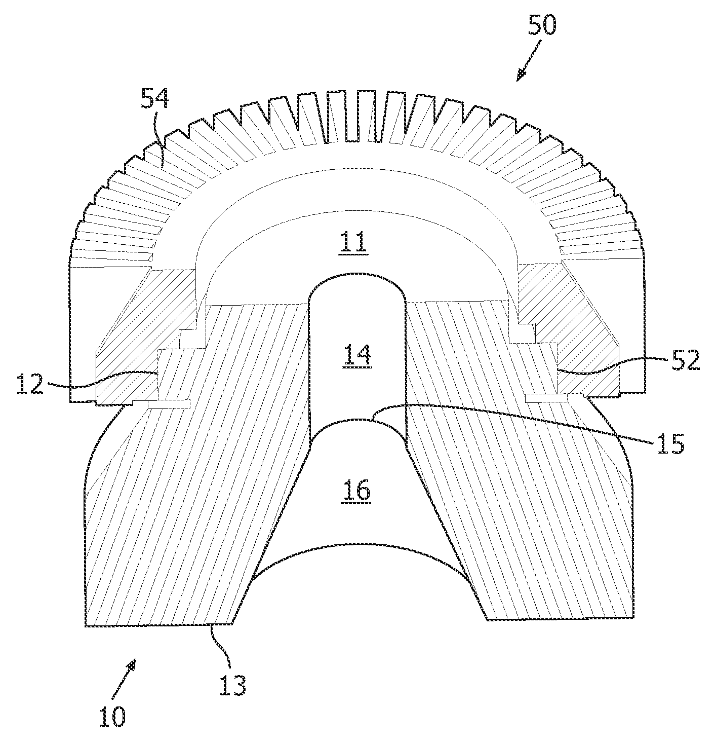
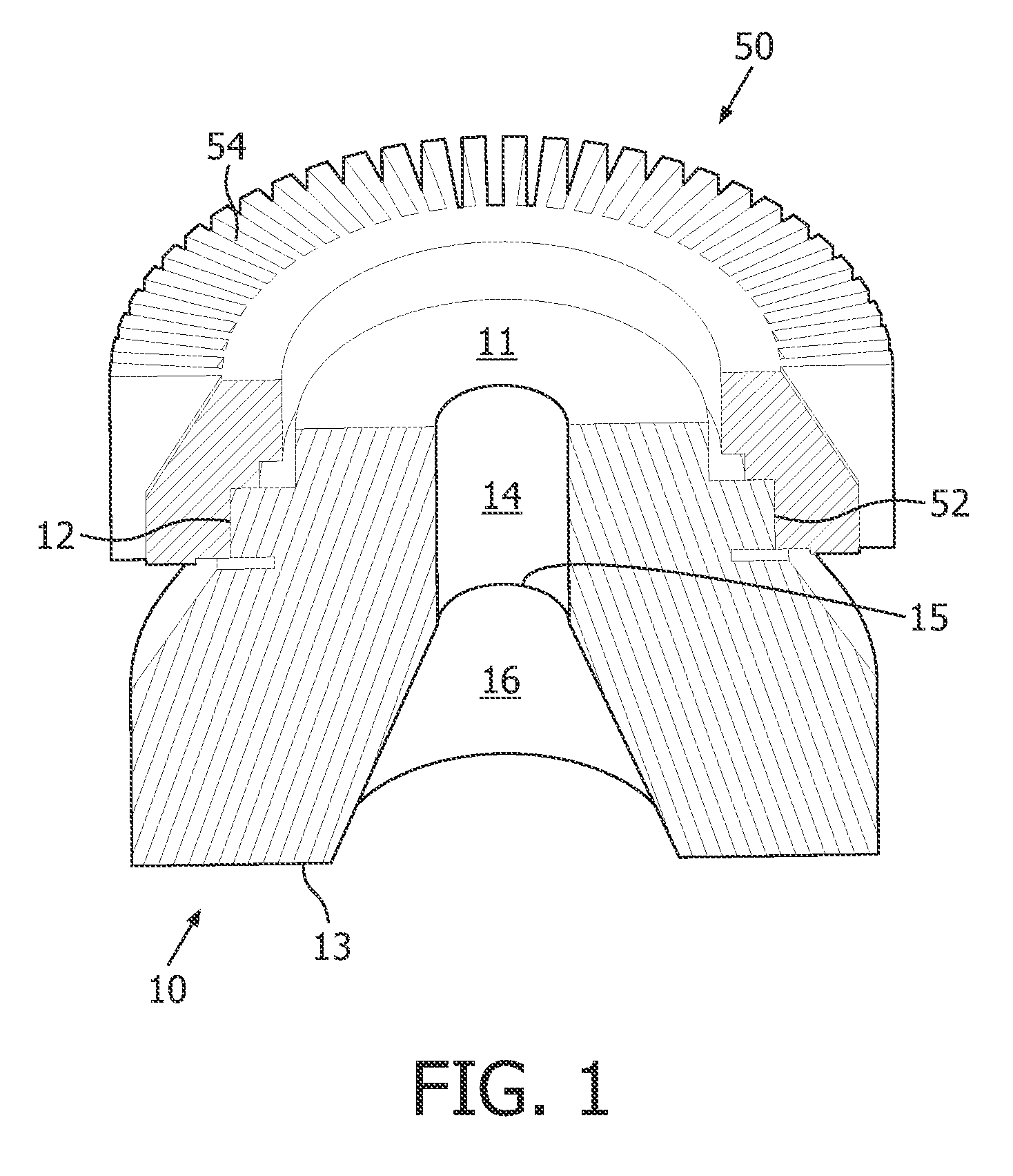
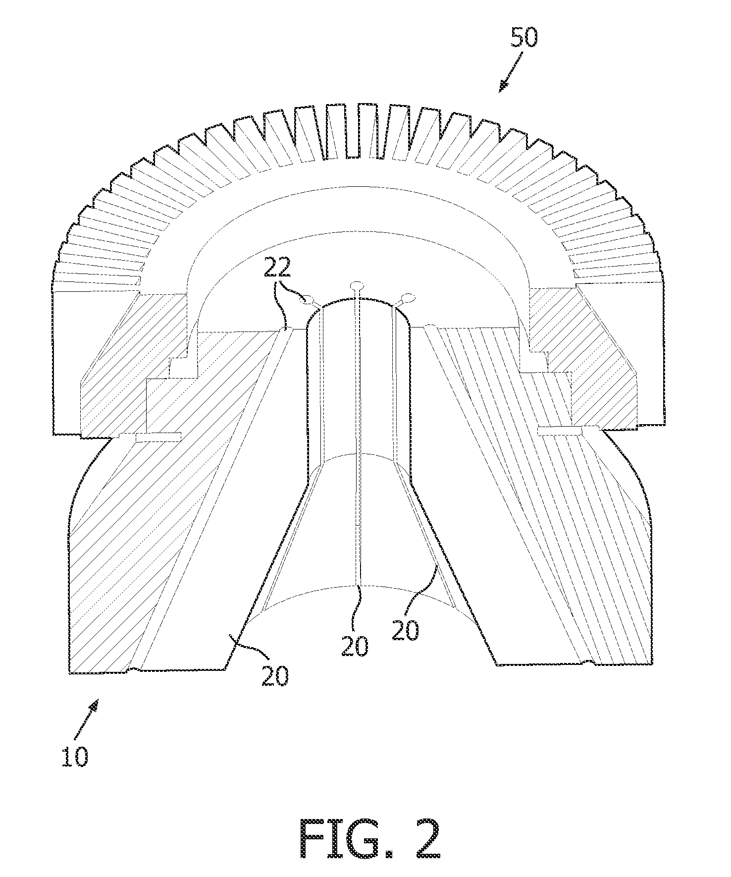
[0038]As mentioned above, it can occur in the heat absorbing member 10 of a SEC, that the inner wall of the heat absorbing member heated up too strongly and therefore tensions are formed in the material. In accordance with the invention the heat absorbing member is provided with at least one slot within its inside. Usually, the heat absorbing member will be provided with a plurality of slots. In accordance with a preferred embodiment the heat absorbing member is provided with eight slots. The slots are formed respectively from the central bore in the direction of the outer periphery of the heat absorbing member.

[0039]As shown in FIGS. 2 to 4, according to a first embodiment, every slot 20 is formed radially from the central bore in the direction to the outside of the heat absorbing member 10. The slots 20 are generally formed not completely though the wall. I.e., each slot 20 includes an end which is open to the central bore, and an end within the heat absorbing member. Each slot ha...

second embodiment

[0041]As shown in FIGS. 5 and 6, in accordance with the invention each of the slots 30 can be formed at an angle with respect to the radial direction. Therefore, the slots 30 start at the central bore in the heat absorbing member and proceeds with an angle to the radial direction, in the direction of the outer periphery of the heat absorbing member. This has the advantage that those electrons which meet the entrance of a slot at the central bore, might be absorbed reliably. The inclined course of each slot makes sure that the electrons impinge a wall which is thick enough to sufficiently absorb the electrons and X-rays.

third embodiment

[0042]As shown in FIGS. 7 and 8, in accordance with the invention each of the slots 40 is formed at a bended course in the heat absorbing member 10. According to said embodiment, the slots 40 are formed firstly in a radial direction starting at the central bore, and then follow a bended course within the material of the heat absorbing member, as exemplarily shown in FIG. 8. Every slot 40 describes a bend between the radial direction and, approximately, the circumferential direction of the heat absorbing member. Therefore it is prevented, on the one hand, that sharp angles result between the central bore and the slots, which angles might lead to an uneven distribution of the heat dissipation within the material. On the other hand, a sufficient material thickness is provided which reliably collects all electrons which are scattered, as well as X-rays. As in all embodiments, a cooling element is provided on the outer side of the heat absorbing member to cool down the heat absorbing mem...


PUM


Abstract

Scattered electron collector comprising a heat absorbing member having a first end, a second end, an outer periphery and a central bore (14, 16), wherein the central bore is formed in longitudinal direction through the heat absorbing member from the first end to the second end, and a cooling element (50) having an outer periphery and an inner periphery (52). The outer periphery (12) of the heat absorbing member is adapted to be in contact with the inner periphery of the cooling element. Further, at least one slot (20) is formed from the central bore in the direction to the outer periphery of the heat absorbing member to reduce compression stress within the heat absorbing member.

Description

[0001]This invention relates generally to a scattered electron collector. Particularly, the invention relates to a scattered electron collector for use in a X-ray tube for generating X-rays.TECHNOLOGICAL BACKGROUND[0002]The future demands for high-end CT and CV imaging regarding the X-ray source are higher power / tube current, smaller focal spots (FS) combined with the ability of active FS size, ratio and position control, shorter times for cooling down, and concerning CT shorter gantry rotation times. In addition to this, the tube design is limited in length and weight to achieve an easy handling for CV application and a realizable gantry setup for CT applications.[0003]One key to reach higher power and faster cooling is given by using a sophisticated heat management concept inside the X-ray tube. In bipolar X-ray tubes about 40% of the thermal load of the target is due to electrons backscattered from the target, which are reaccelerated towards the target and hitting it again outsid...

Claims


Application Information

Patent Timeline
Patent Type & Authority Applications(United States)
IPC IPC(8): H01J35/02
CPCH01J2235/168H01J35/16
Inventor HAUTTMANN, STEFAN
Owner KONINKLIJKE PHILIPS ELECTRONICS NV
Learn More