
Secondary cell and its manufacturing method

a manufacturing method and technology for secondary batteries, applied in the direction of cell components, sustainable manufacturing/processing, wound/folded electrode electrodes, etc., can solve the problems of reducing charge/discharge capacity, affecting the cycle life of the battery, so as to reduce the cycle life, prevent the peeling of active materials, and suppress the occurrence of internal short circuits

Inactive Publication Date: 2010-11-04
GK BRIDGE 1
View PDF3 Cites 11 Cited by
  • Summary
  • Abstract
  • Description
  • Claims
  • Application Information

AI Technical Summary

Benefits of technology

[0031]According to the present invention, curvature portions are provided at side edges and bottom centers of trenches formed in the surface of an electrode plate so that peeling of an active material can be prevented. In this manner, it is possible to suppress occurrence of an internal short circuit and a decrease in cycle life. In addition, the pitch of trenches formed in both faces of the electrode plate is adjusted to 200 μm or less, so that bending of the electrode plate can be suppressed, thus allowing suppression of a decrease in cycle life caused by peeling of the active material layer from a core material (i.e., a current collector). Accordingly, a high capacity secondary battery exhibiting superior impregnating ability for an electrolyte, excellent cycle characteristics, and high reliability can be implemented.

Problems solved by technology

However, when the electrode group is pressed to hardly leave a gap between the electrode plates and the separator, it disadvantageously takes a long time to impregnate the entire electrode group with an electrolyte after pouring the electrolyte into the battery case.
This problem is conspicuous especially for nonaqueous electrolytes used for lithium ion secondary batteries because of high viscosity of the nonaqueous electrolytes.
However, the amount of the mixture layer decreases in this case, so that charge / discharge capacity decreases.
The trenches formed in the surface of the electrode plate can cause breakage of the electrode plate during formation of an electrode group by winding the electrode plate.

Method used


Image

  • Secondary cell and its manufacturing method
  • Secondary cell and its manufacturing method
  • Secondary cell and its manufacturing method

Examples


example

[0094]Hereinafter, evaluation results on cycle characteristics and impregnating ability, for example, of the lithium ion secondary battery of the present invention will be described based on examples. The present invention is not limited to the following examples. (Example 1)

[0095]First, 100 parts by weight of lithium cobaltate as an active material, 2 parts by weight of acetylene black as a conductive agent with respect to 100 parts by weight of the active material, and 2 parts by weight of polyvinylidene fluoride as a binder with respect to 100 parts by weight of the active material were stirred and kneaded with an appropriate amount of n-methyl-2-pyrrolidone, thereby producing a positive electrode material mixture paste. This positive electrode material mixture paste was applied onto a current collector made of aluminium foil with a thickness of 15 μm, was dried, and then was pressed to have a total thickness of 170 μm.

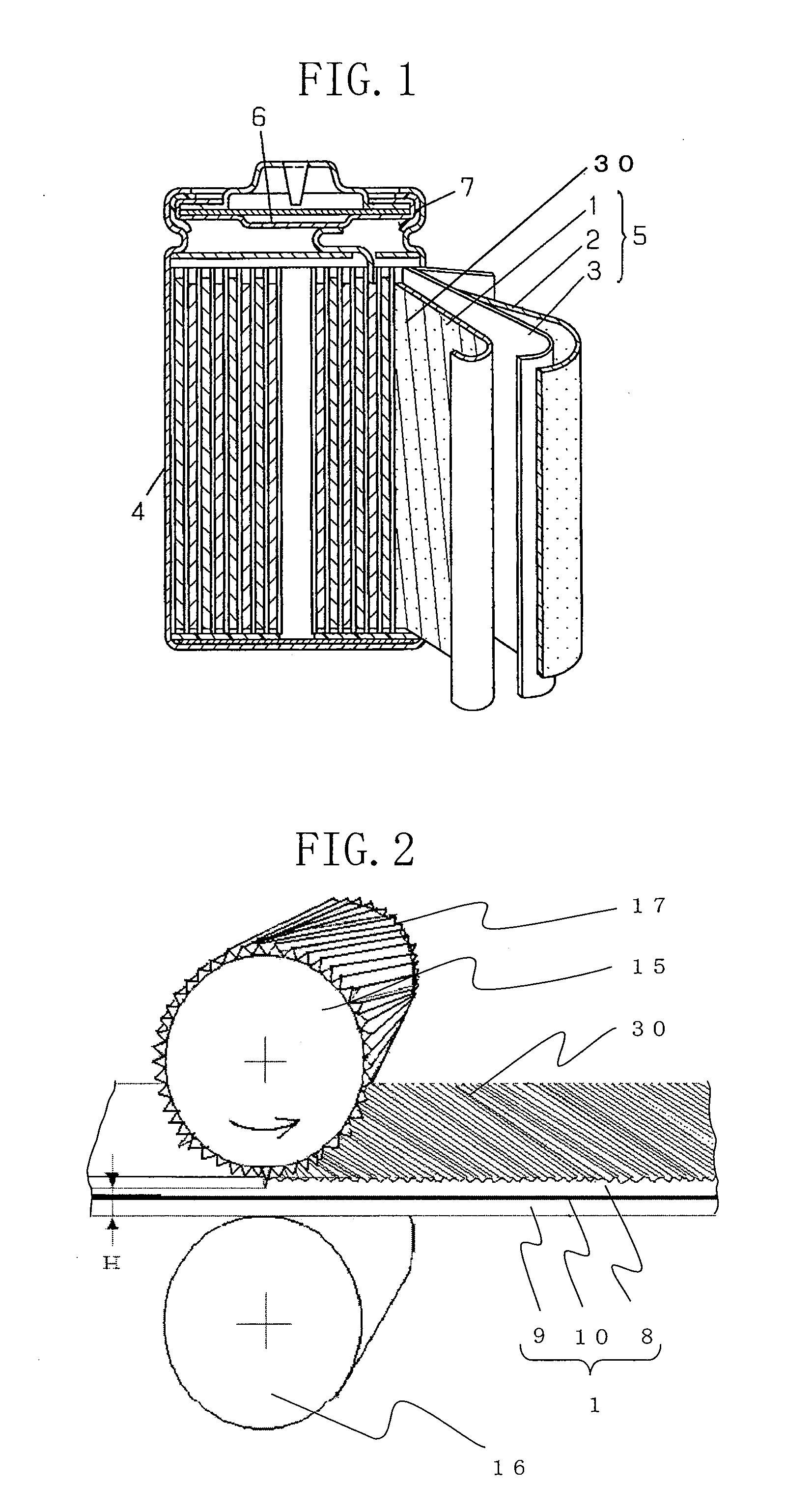
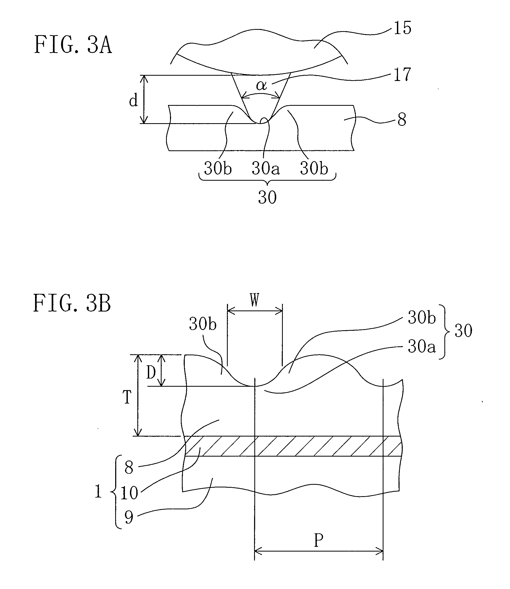
[0096]Next, as illustrated in FIG. 3(a), an upper roller 15 o...

example 2

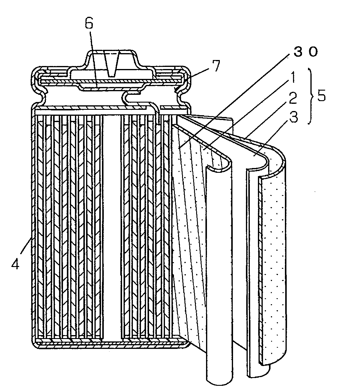
[0101]An electrode group was produced in the same manner as in Example 1 except that a lower roller 16 was equivalent to the upper roller 15 used in Example 1 so that trenches 30 were formed in both faces of a positive electrode plate 1. As illustrated in FIG. 6(a), the trenches 30 formed on the both faces of the positive electrode plate 1 are positioned at an angle of 45° with respect to the longitudinal direction of the positive electrode plate 1 and the phases of the trenches in the respective both faces of the positive electrode plate 1 are symmetric.


PUM

PropertyMeasurementUnit
depthaaaaaaaaaa
depthaaaaaaaaaa
inclination angleaaaaaaaaaa

Abstract

A secondary battery includes an electrode group 5 formed by winding a positive electrode plate 1 and a negative electrode plate 2 with a separator 3 interposed therebetween. Each of the positive and negative electrode plates 1 and 2 includes a current collector 1 and mixture layers 8 and 9 each containing an active material and formed on the surface of the current collector 1. A plurality of trenches 30 are formed in the surfaces of the mixture layers 8 and 9 of at least one of the positive electrode plate 1 and the negative electrode plate 2. The trenches 30 have curvature portions at side edges 30b and bottom centers 30a thereof.

Description

TECHNICAL FIELD[0001]The present invention relates to secondary batteries (cells) in each of which a positive electrode plate and a negative electrode plate are wound or stacked with a separator interposed therebetween, and particularly relates to a high capacity secondary battery exhibiting excellent impregnating ability for an electrolyte and a method for manufacturing such a battery.BACKGROUND ART[0002]Lithium ion secondary batteries, which are now widely used as power supplies for mobile electronic equipment, have achieved high potential and high capacity by employing, as active materials for negative electrodes, carbon materials capable of inserting and extracting lithium and by employing, as active materials for positive electrodes, composite oxides of transition metal and lithium, e.g. LiCoO2. However, further increase in capacity is required with an increased range of functions of recent electronic equipment and communication equipment.[0003]For example, to increase the capa...

Claims


Application Information

Patent Timeline
Patent Type & Authority Applications(United States)
IPC IPC(8): H01M6/10H01M6/00H01M4/13H01M4/139H01M10/0525H01M10/0587H01M10/36
CPCH01M4/13H01M4/139H01M10/0431Y10T29/49108H01M10/0587Y02E60/122H01M10/0525Y02E60/10Y02P70/50H01M4/0435H01M2004/021
Inventor KUMAKARI, HIDEYUKIKATOU, SEIICHI
Owner GK BRIDGE 1
Learn More