Method and apparatus to estimate location and orientation of objects during magnetic resonance imaging

a magnetic resonance imaging and location estimation technology, applied in the field of methodology and equipment, can solve the problems of inability to directly use the methodology, inability to estimate the location and orientation of objects during magnetic resonance imaging, and inability to accurately estimate the location and orientation of objects, etc., and achieve the effect of limited accuracy of orientation estimation and accurate orientation

Active Publication Date: 2010-11-04
SOREK MEDICAL SYST LTD
View PDF5 Cites 15 Cited by
  • Summary
  • Abstract
  • Description
  • Claims
  • Application Information

AI Technical Summary

Benefits of technology

[0030]The present invention has significant advantages over existing methodologies. Compared with stereotaxis, either the frame or frameless techniques, the new methodology enables the use of devices like catheters or surgical instrumentation without the need for direct line of sight with the device and under realtime MRI. Unlike the remote electromagnetic localization methodology of Acker et al the present invention is based on measurement of voltages induced by a set of time-varying electromagnetic gradient fields in a set of coils (Faraday Law), rather than the need to use activations of homogenous electromagnetic fields and gradient electromagnetic fields which induce voltages in a set of miniature conductors carrying electrical current (Hall effect). Thus, the present invention is totally passive, it does not require any excitation of the sensors, and the requirement for time-variable magnetic fields may be satisfie

Problems solved by technology

Yet both the stereotaxis and the frameless techniques are typically limited to the use of rigid devices like needles or biopsy forceps since their adequate operation requires either mechanical attachments or line of sight between the light sources and the sensors.
This methodology cannot be directly used during MRI because the application of an external electromagnetic field creates an unacceptable level of image artifacts.
The addition of conducting elements to the scanner (the coils of the generators) may result in substantial artifacts due to the creation of eddy currents and may create electromagnetic interference with the scanner.
As with the previous methodology, the application of the technology to MRI is problematic due to the simultaneous use of RF signals by the MR scanning.
Potential difficulties are the heating of the receiving antenna in the device by the high amplitude excitation RF transmissions of the MRI scanner and artifacts in the MR image.
This substantially complicates the programming of the pulse sequence of the scanner (due to the need to add RF and gradient activations for tracking that interfere with the imaging sequence), lengthens the time of scan, and limits the update rate of tracking.
Additional major limitations of this tracking technique include the potential heating of the RF coils, especially inside the body; and the need to determine the orientation indirectly through the use of estimated location of at least 2 separate RF coils, with limited accuracy when small

Method used


Image

  • Method and apparatus to estimate location and orientation of objects during magnetic resonance imaging
  • Method and apparatus to estimate location and orientation of objects during magnetic resonance imaging
  • Method and apparatus to estimate location and orientation of objects during magnetic resonance imaging

Examples


Embodiment Construction

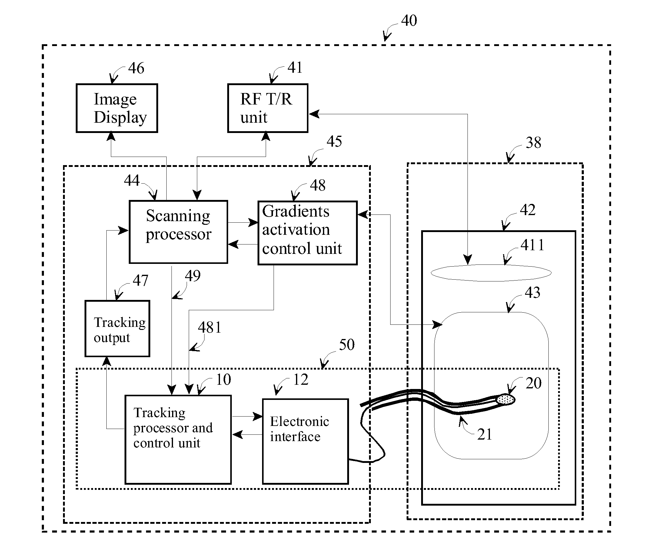
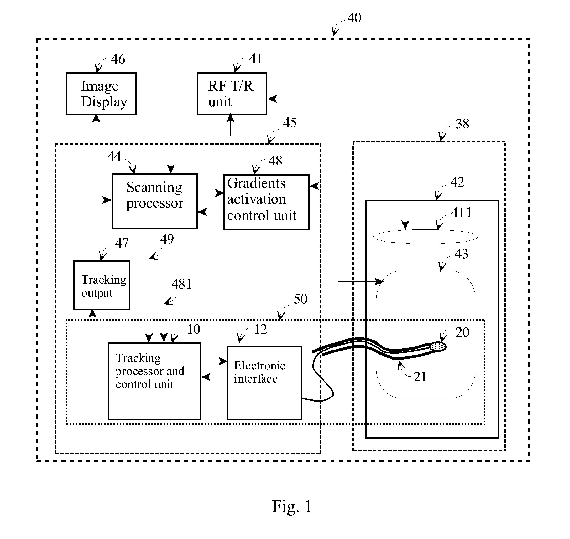
[0040]Tracking based on the gradient fields of magnetic resonance imaging (MRI) scanners is disclosed in U.S. Pat. No. 6,516,213 by Nevo. This technology is based on passive operation of the tracking system without any change of the scanner's hardware or mode of operation. To achieve better tracking performance, a technique to create a custom MRI pulse sequence is disclosed. Through this technique any standard pulse sequence of the scanner can be modified to include gradient activations specifically designated for tracking. These tracking gradient activations are added in a way that does not affect the image quality of the native sequence. The scan time may remain the same as with the native sequence or longer due to the additional gradient activations. The tracking system itself can use all the gradient activations (gradient activations for imaging and gradient activations for tracking) or eliminate some of the gradients and lock onto the specific gradient activations that are adde...


PUM


Abstract

Tracking based on the gradient fields of magnetic resonance imaging (MRI) scanners based on passive operation of the tracking system without any change of the scanner's hardware or mode of operation. To achieve better tracking performance, a technique to create a custom MRI pulse sequence is disclosed. Through this technique any standard pulse sequence of the scanner can be modified to include gradient activations specifically designated for tracking. These tracking gradient activations are added in a way that does not affect the image quality of the native sequence. The scan time may remain the same as with the native sequence or longer due to the additional gradient activations. The tracking system itself can use all the gradient activations (gradient activations for imaging and gradient activations for tracking) or eliminate some of the gradients and lock onto the specific gradient activations that are added to the custom pulse sequence.

Description

FIELD OF THE INVENTION[0001]The present invention relates to methodology and apparatus to determine the location and orientation of an object, for example a medical device, located inside or outside a body, while the body is being scanned by magnetic resonance imaging (MRI). More specifically, the invention enables estimation of the location and orientation of various devices (e.g. catheters, surgery instruments, biopsy needles, etc.) by measuring electrical potentials induced by time-variable magnetic fields in a set of miniature coils.BACKGROUND OF THE INVENTION[0002]Minimally invasive procedures: Minimally-invasive diagnostic or interventional procedures require either direct visual viewing or indirect imaging of the field of operation and determination of the location and orientation of the operational device. For example, laparoscopic interventions are controlled by direct viewing of the operational field with rigid endoscopes, while flexible endoscopes are commonly used for di...

Claims


Application Information

Patent Timeline
IPC IPC(8): A61B5/055
CPCG01R33/287G01R33/028
Inventor ROTH, ABRAHAMNEVO, EREZ
Owner SOREK MEDICAL SYST LTD
Why Eureka
Try Eureka