Device and method for compensating color shifts in fiber-optic imaging systems

a fiber-optic imaging and compensating device technology, applied in the field of devices and methods for compensating color shifts, can solve the problems of affecting the use of such devices, unable to achieve an actual increase in image resolution, and many applications in the field of diagnostics, inspection, quality assurance and research, etc., to achieve the effect of increasing image quality

Inactive Publication Date: 2010-11-04
FRIEDRICH ALEXANDER UNIV ERLANGEN NURNBERG +1
View PDF8 Cites 6 Cited by
  • Summary
  • Abstract
  • Description
  • Claims
  • Application Information

AI Technical Summary

Benefits of technology

[0024]When using sensors for non-visible spectral regions, visualization can be effected byway of false-color representation, or simple mapping of the non-visible spectral region to the visible spectral region can be used for visualizing, and for example using for medical diagnostics, the intensity values acquired in the non-visible spectral region. Thereby, even when using non-visible electromagnetic waves, the image quality is increased significantly, because smaller details, which could otherwise be masked by the color noise, are recognizable in the capture, or become recognizable when using the inventive concept.
[0025]Independently of the spectral region used, it is also advantageous for motion recognition, which may be performed on the basis of the ascertained intensity values, if the corruption of color values can be prevented. Here, the motion recognition may also be based on intensity or color values acquired in the non-visible spectral range.

Problems solved by technology

Without the employment of endoscopes for imaging, many applications in the field of diagnostics, inspection, quality assurance and research, among others, would be impossible today.
The reduced resolution caused thereby, or the honeycomb structure recorded by the sensor due to the arrangement of the light fiber, partially inhibit the use of such devices.
Just like the smoothing of the honeycombed cladding structures or by way of its masking in the Fourier space, however, these methods, although increasing the quality of representation of the captured image, have the disadvantage of failing to achieve an actual increase in resolution of the image.
Regarding color fidelity of the produced images, however, this procedure does not lead to optimum results.
If an image that is produced in such a way, for example, is to be used for further visual use, assessment of image data or extraction and processing of color features, this is achieved only to an unsatisfactory extent, owing to the color shifts resulting from a simple combination of a fiberscope with a color camera.
This approach fails because of the false colors caused by the pattern of the sensor elements with different spectral sensitivity and the non-uniform illumination of the sensor elements by an individual optical fiber.
As will be explained in greater detail further below, non-uniform illumination of such a color pattern, and image processing electronics of the color camera optimized for uniform illumination, leads to the sensor and / or the color camera producing false-color image information for the sensor elements illuminated by a single optical fiber.
The problem is further aggravated in the digitization of the image by a fiber bundle, because the imaging faces a trade-off.
However, determination of a color value would only be possible for one color component for the corresponding fiber.
However, an undesired color shift results from the imbalance of stimulated sensor elements following the conversion of raw intensity data of the Bayer pattern to color values.
Assuming uniform illumination (as underlying the algorithm operating in a color camera), if a color value and / or several color values are computed from the pixels thus illuminated, this inevitably leads to an undesired color shift.
This color shift is perceived as extremely disturbing by the observer and also leads to further undesired effects through abrupt color changes (features in the image).
For example, if motion compensation and / or motion estimation is to be performed due to such a false-color image, this is hardly possible, because the motion estimation is particularly based on finding identical intensity patterns in different image regions of various consecutive captures.
If the individual captures per se have false colors, i.e. have corrupted intensities, the motion compensation algorithm cannot achieve any reliable result either.

Method used


Image

  • Device and method for compensating color shifts in fiber-optic imaging systems
  • Device and method for compensating color shifts in fiber-optic imaging systems
  • Device and method for compensating color shifts in fiber-optic imaging systems

Examples


Embodiment Construction

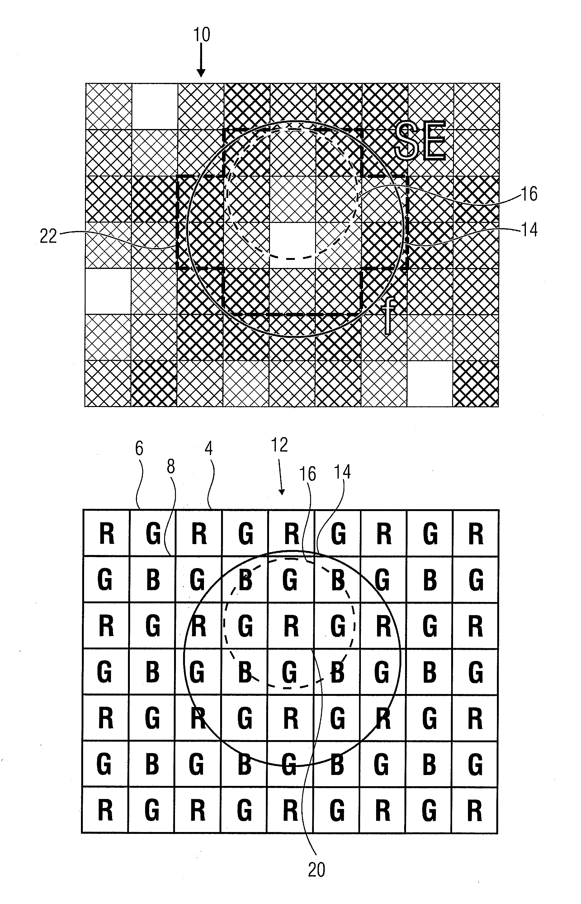
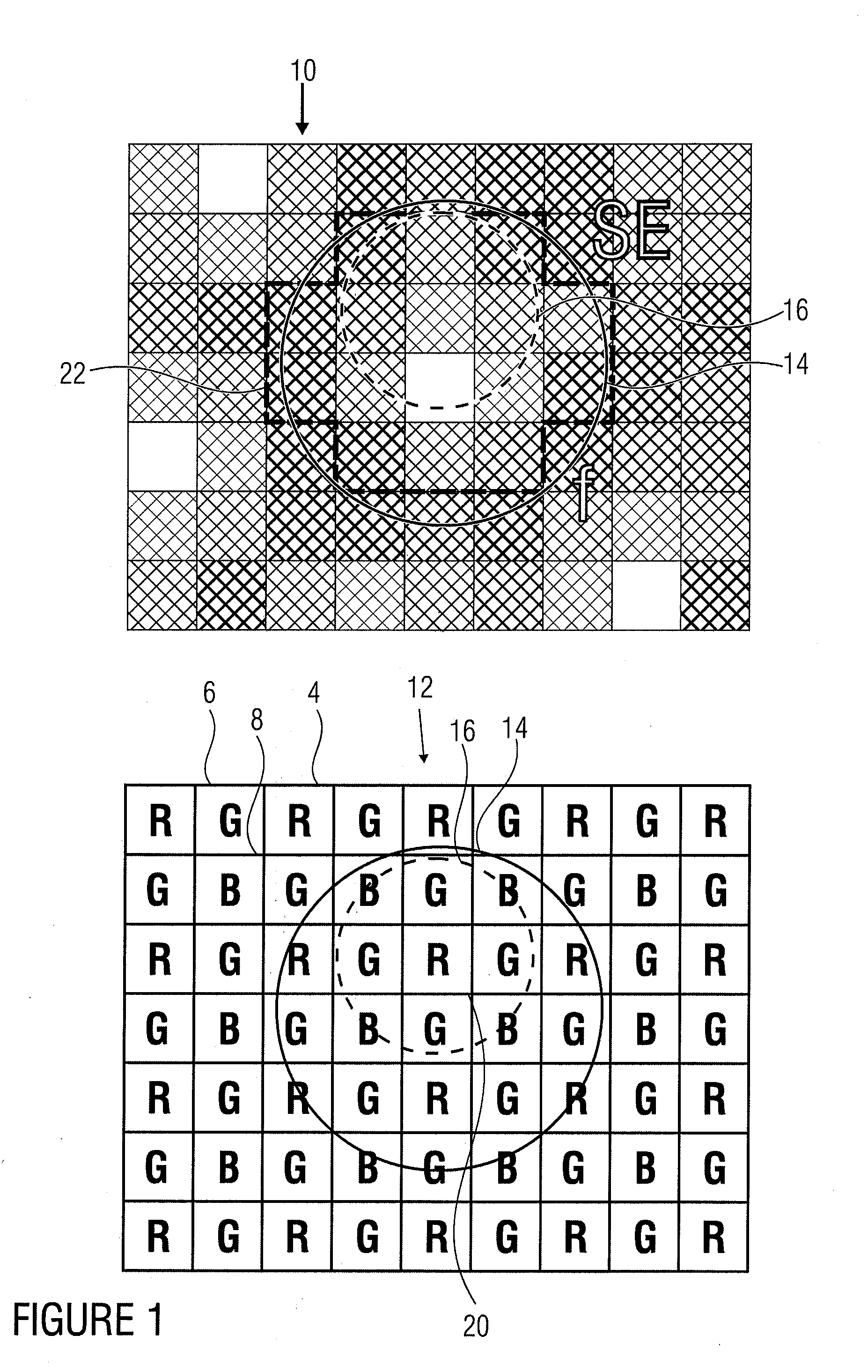
[0037]By way of example, FIG. 1 shows the image of an optical fiber on the surface of a sensor element arrangement consisting of sensor elements of different spectral sensitivities. By way of example, without limitation of general meaning, there is illustrated a sensor with sensor elements arranged in matrix shape, which are sensitive to red (sensor element 4 marked R, for example), green (sensor element 6 marked G, for example) and blue (sensor element 8 marked B, for example). In the arrangement shown in FIG. 1, the red, green and blue-sensitive pixels and / or sensor elements are arranged in the so-called Bayer pattern. This arrangement is to be construed as merely exemplary. Further embodiments of the invention may be based on any sensor arrangement, for example on matrix-shaped sensor arrangements with another geometric arrangement of the sensor elements sensitive to different spectral regions. Also, the individual sensor elements do not have to be square-shaped, they may be para...


PUM


Abstract

A color value for an optical fiber of a fiberscope can be generated on the basis of the intensity values of a plurality of sensor elements of a sensor element arrangement that are sensitive to one spectral region each from a set of sensor spectral regions, if calibration values are provided for each of the spectral regions associated with the optical fiber. The intensity values of all sensor elements of the respective spectral region that are illuminated by the light guide can be combined with the provided calibration values, in order to obtain the color value associated with the optical fiber, which correctly reproduces the color of the light transported by the optical fiber.

Description

[0001]This application is a U.S. national entry of PCT Patent Application Serial No. PCT / EP2008 / 003189 filed 21 Apr. 2008, and claims priority to German Patent Application No. 102007026595.8-51 filed Jun. 8, 2007, each of which is incorporated herein by reference.BACKGROUND OF THE INVENTION[0002]The present invention concerns a device and a method for compensating for color shifts, as arise when employing fiberscopes with color picture cameras.[0003]Optical systems in which an image is transferred to an imaging sensor by optics are in widespread use. Without the employment of endoscopes for imaging, many applications in the field of diagnostics, inspection, quality assurance and research, among others, would be impossible today. On the one hand, refractive optical systems are used here, i.e. systems with a rigid construction within which the image is transmitted onto the sensor through a lens arrangement, similar to an objective of a camera. On the other hand, fiber-optic systems ar...

Claims


Application Information

Patent Timeline
Patent Type & Authority Applications(United States)
IPC IPC(8): G01J3/46G06F19/00
CPCG02B27/0025G02B23/26
Inventor WINTER, CHRISTIANZERFASS, THORSTEN
Owner FRIEDRICH ALEXANDER UNIV ERLANGEN NURNBERG
Why Eureka
Try Eureka