
System and Method for Extraction of Petroleum from Oil/Water Mixture

a technology of oil/water mixture and extraction method, which is applied in the nature of treatment water, separation process, chemistry apparatus and processes, etc., can solve the problems of inability to use shallow water, design is overwhelmingly inappropriate for spill clean-up, and is not suitable for shallow water use. , to achieve the effect of restoring the nation's oil spill protection resources

Inactive Publication Date: 2010-11-11
ABRAHAM CHARLES
View PDF20 Cites 4 Cited by
  • Summary
  • Abstract
  • Description
  • Claims
  • Application Information

AI Technical Summary

Benefits of technology

The present invention provides a novel method for extracting petroleum and other oils from an oil / water mixture, particularly from a spill in a water source. The method involves using an absorbent belt skimming and an on-board oil tank to separate the oil from the water. The separated oil can then be re-sold or re-used. The invention also includes a lid for the oil tank to prevent bacterial growth and a system for recycling the water. The invention can be easily adapted for use in various situations, such as oil spills in waterways or on-board oil tankers. It is cost-efficient and environmentally friendly.

Problems solved by technology

Technology for these inventions is centered on using vast collection means such as large sea nets or even an entire self-contained barge system to remove the oil by large scale recapture / destroy boom and skimmer systems and is extremely expensive.
Yet, while these systems are effective for bulk oil spills with an unrestrained quantity of area and within which to operate and an unrestrained budget, these designs would be overwhelmingly inappropriate for use in spill clean-ups in close, shallow waters such as coastal and inland waterways, rivers, and canals.
Yet a model such as this cannot be used in shallow waters with the depth necessary to support the floating watercraft and is also limited in maneuverability in confined areas.
Additionally, the use of a pumping system creates concerns of clogging and related issues when the hose is deployed underneath the water surface.
Particularly in shallow waters, an overabundance of liquid and solid substances collect near the surface of the water causing murkiness and congestion that could lead to blockage of the pump or hose.
Consequently, this method is somewhat ineffective in working within the confined work area of an inland waterway or river.
Yet, what these inventions lack in their application is the complete integration of both method and hardware to conform to the environmental surroundings and facilitate not only the extraction of the oil from the affected area but the preservation of that petroleum for future use and, more importantly, the reintegration of the affected (and subsequently cleaned) water safely back into its source so as to harm the environment in the least way possible.
Traditional Ocean Oil Spill Removal Organizations (OSROs) are ill-equipped, inexperienced, and / or inadequately trained in responding to oil spill accidents impacting cultural and environmental freshwater and / or saline estuary waterways caused by the following and other potential sources: bulk storage tanks located next to canals, rivers: and other inland waterways; canal barge routes; Hazmat truck routes; highways having petroleum truck routes; onshore oil processing facilities; petroleum pipelines; railroad crossings; river barge routes.
Existing methods of oil spill accident petroleum evaporation trigger loss of lighter material rendering petroleum hydrocarbons denser than water, so that it sinks to the bottom of canals, lakes, and rivers where it sedimentizes into tar mats and tar logs, enormously complicating the recapture / destruction of the petroleum.
Dispersion of an oil spill with chemical agents that emulsify, disperse, or solubilize petroleum hydrocarbons into the water column or that promote surface spreading of oil slicks to facilitate dispersal of oil into the water column severely challenges sensitive wetlands and freshwater ecosystems.
In situ burning of oil slicks and spills unleashes an immediate release of hydrocarbon pollutants into the atmosphere and presents still poorly understood and inadequately researched longitudinal effects for adjacent ecosystems and population centers.
Coastal and inland oil spill burn off thereby poses potential non-compliance with the National Pollutant Discharge Elimination System regulatory program and State Water Quality Standards, since existing in-stream water uses may be significantly altered.

Method used


Image

  • System and Method for Extraction of Petroleum from Oil/Water Mixture
  • System and Method for Extraction of Petroleum from Oil/Water Mixture
  • System and Method for Extraction of Petroleum from Oil/Water Mixture

Examples


Embodiment Construction

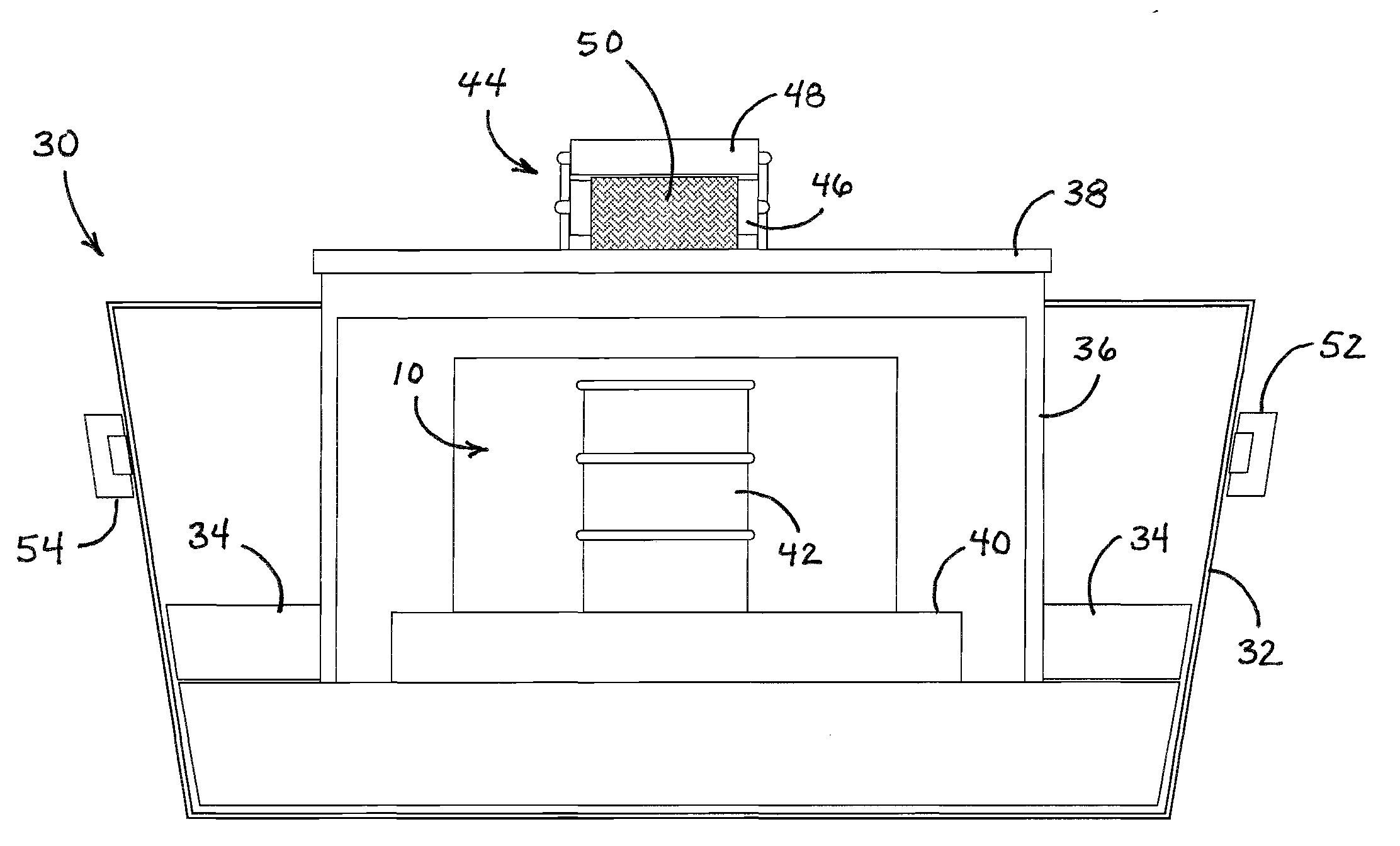
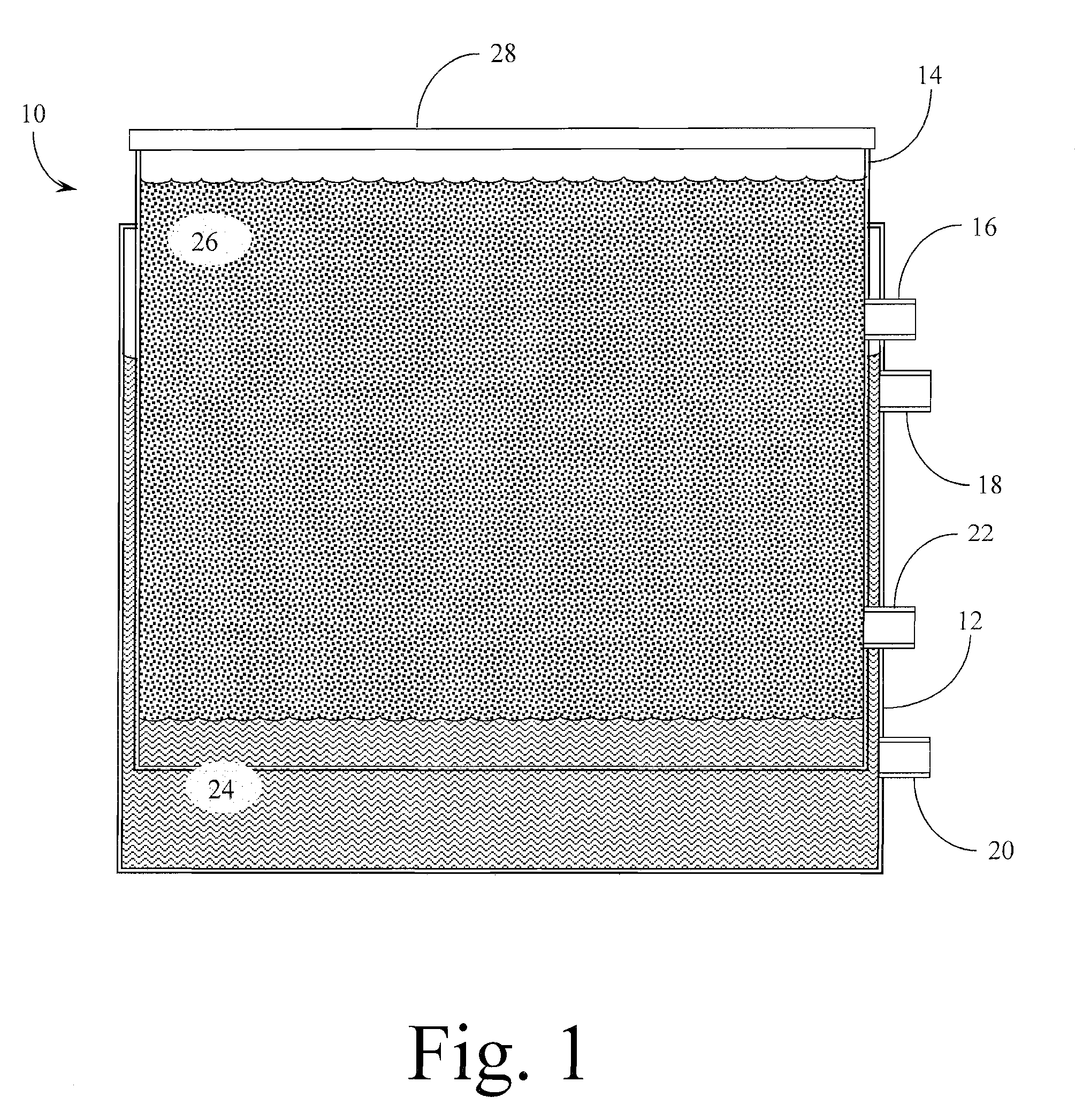
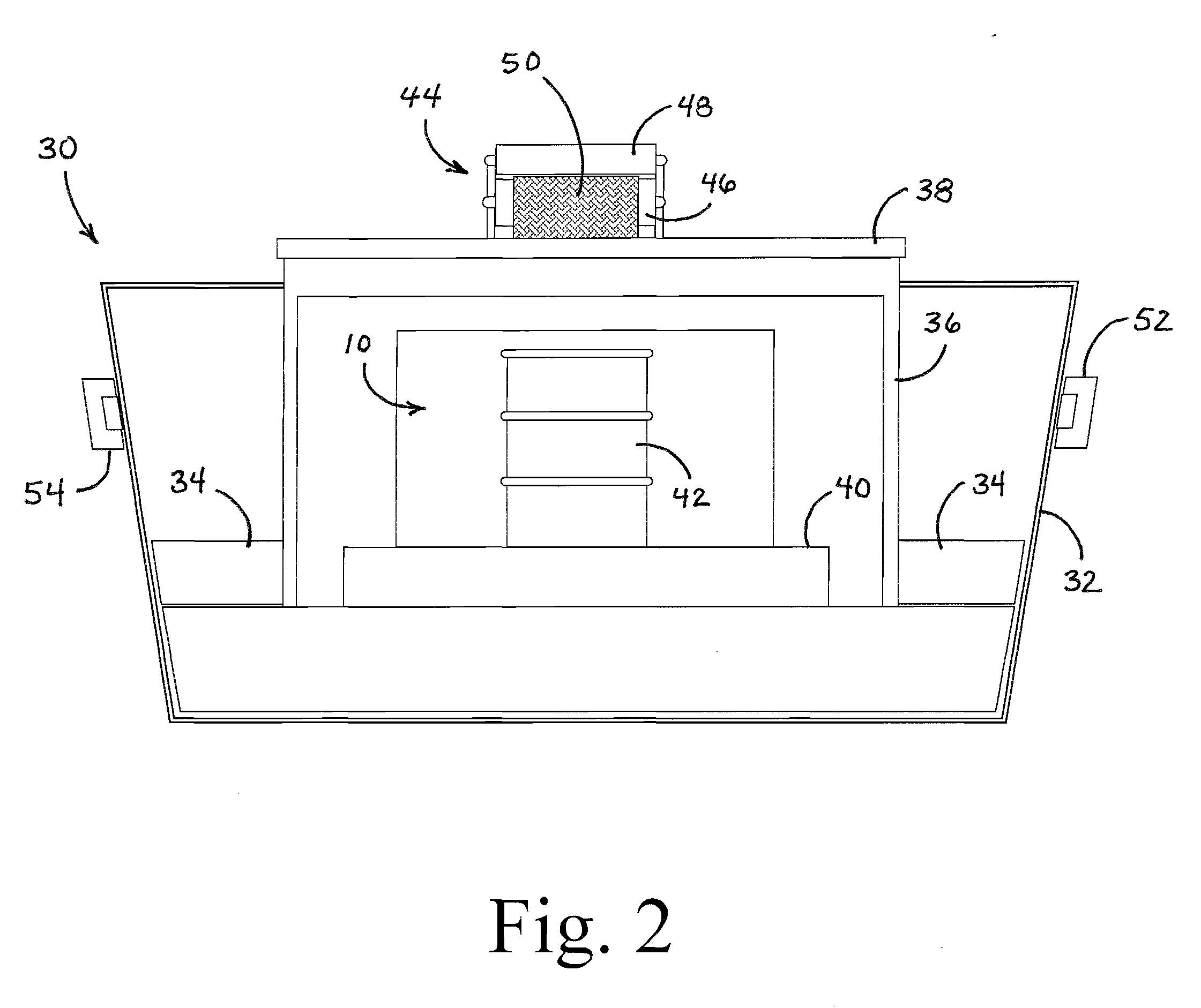
[0034]FIG. 1 is a cross sectional view cut away of the invention, the petroleum Extraction Receptacle housed within an Exterior Container. Claimed invention 10, the form for the petroleum Extraction Receptacle 14 housed within an Exterior Container 12. Wall of Exterior Container 12 (the invention). Wall of petroleum Extraction Receptacle (the invention) 14. The petroleum exit 16 from the invention, the petroleum Extraction Receptacle through wall of same and attaching to an external faucet and pipe for drainage into an oil drum or VOSS (floating bladder.) Residual water-exit faucet and pipe 18 for drainage into a second petroleum Extraction Receptacle (the invention). Residual water drain 20 for cleaning the Exterior Container. Residual petroleum drain 22 through both walls for cleaning the petroleum Extraction Receptacle. Residual water 24 forced out the bottom-less Extraction Receptacle 14 by the petroleum extracted. Extracted petroleum 26 within the Extraction Receptacle 14. Lid ...


PUM

PropertyMeasurementUnit
oleophilicaaaaaaaaaa
density/specific gravityaaaaaaaaaa
massaaaaaaaaaa

Abstract

A petroleum from oil / water mixtures extraction method for use as an adjunct to current stationary active second containment methods for industrial oil spill accidents, and as an adjunct to currently used equipment for residual oil removal in clean-out measures for, among others: canal barges, hazmat trucks, oil storage tanks, oil tankers, oil transportation railroad cars, river barges, as an on-board separation system for petroleum based bilge, and in coastal and inland waterways clean-up from oil spill accidents.

Description

CROSS REFERENCE TO RELATED APPLICATIONS[0001]This application claims the benefit under Title 35 United States Code §119(e) of U.S. Provisional Patent Application Ser. No. 61 / ______; filed May, ______, 2008; the full disclosure of which is incorporated herein by reference.BACKGROUND OF THE INVENTION[0002]1. Field of the Invention[0003]The present invention relates generally to a method of extracting petroleum from an oil / water mixture through the removal and clean-up of an oil spill in point sources such as a lake or river. The present invention relates more specifically to utilizing a conveyor belt method to extract the oil / water mixture, funneling it into large extraction receptacles from whence the oil and water are separated through the principle of fluid dynamic application of Stoke's Law in which the difference in density / specific gravity of the two substances causes the petroleum to rise to the top of the receptacle and separate from the residual water.[0004]2. Description of ...

Claims


Application Information

Patent Timeline
Patent Type & Authority Applications(United States)
IPC IPC(8): C02F1/26
CPCB01D17/0202B01D17/0208C02F2201/001C02F2103/008C02F1/40
Inventor ABRAHAM, CHARLES
Owner ABRAHAM CHARLES
Learn More