Miniature Fourier Transform Spectrometer and Method of Operation

a transform spectrometer and transform technology, applied in the direction of optical radiation measurement, interferometric spectrometry, instruments, etc., can solve problems such as construction interference at a detector

Inactive Publication Date: 2010-11-11
BLOCK ENG
View PDF20 Cites 13 Cited by
  • Summary
  • Abstract
  • Description
  • Claims
  • Application Information

AI Technical Summary

Problems solved by technology

When the two paths differ by a whole number of wavelengths, for example, there is constructive interference at a detector.

Method used


Image

  • Miniature Fourier Transform Spectrometer and Method of Operation
  • Miniature Fourier Transform Spectrometer and Method of Operation
  • Miniature Fourier Transform Spectrometer and Method of Operation

Examples


Embodiment Construction

[0027]MEMS Interferometer

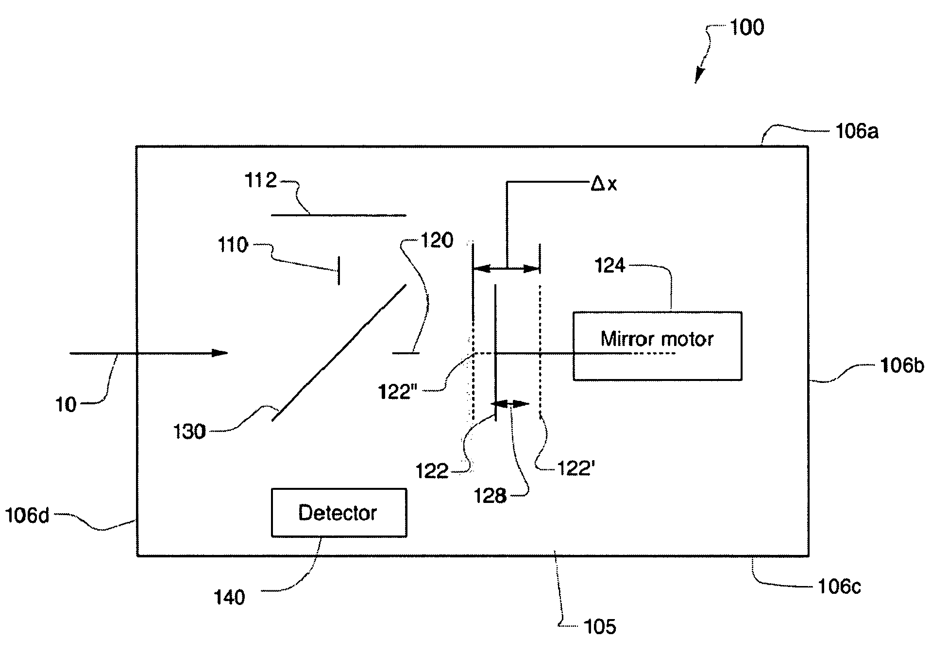
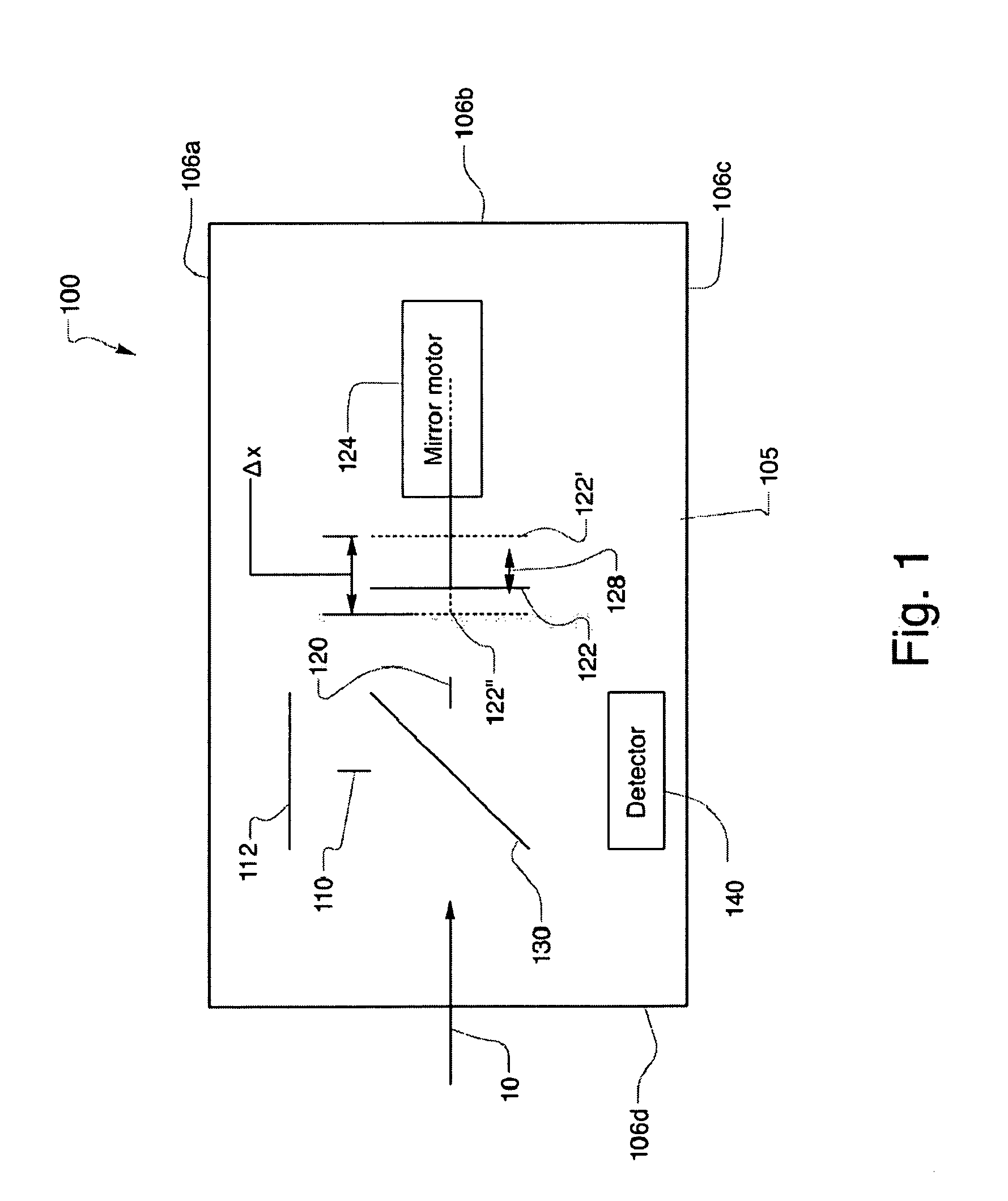
[0028]FIG. 1 shows an interferometer system 100, which has been constructed according to the principles of the present invention. In the illustrated example, the interferometer system 100 is used to analyze the incoming light 10.

[0029]The interferometer system 100 is constructed on an optical bench 105. The optical bench is unitary piece of MEMS substrate material. Typically, the bench 105 is silicon and / or silicon nitride wafer material that has been diced by cleaving or die sawing along edges 106a, b, c, d to create the individual chips or microoptical benches 105.

[0030]The interferometer system 100 comprises two beam paths or two arms that extend parallel to a top surface of the optical bench 105: a fixed mirror arm 110 and a moving mirror arm 120. A beam splitter 130 divides the incoming light 10 between the two arms 110, 120 in the illustrated Michelson interferometer configuration.

[0031]In alternative embodiments, the mirrors and possibly beam splitter...


PUM

PropertyMeasurementUnit
diameteraaaaaaaaaa
diameteraaaaaaaaaa
diametersaaaaaaaaaa

Abstract

A Micro-Electro-Mechanical Systems (MEMS) interferometer is implemented in a Fourier transform spectrometer, which includes a common housing containing the interferometer and a gas cell, possibly including a preconcentrator. The interferometer system includes an optical bench and at least two mirror structures, being patterned from one or more layers on the optical bench and erected to extend substantially perpendicularly to the bench to define two interferometer arms to provide a MEMS interferometer.

Description

RELATED APPLICATIONS[0001]This application claims the benefit under 35 USC 119(e) of U.S. Provisional Application No. 60 / 987,971, filed on Nov. 14, 2007, and is related to U.S. application Ser. No. ______, filed on an even date herewith, by the same inventors, entitled MEMS Michelson Interferometer and Method of Fabrication, both of which are incorporated herein by this reference in their entirety.BACKGROUND OF THE INVENTION[0002]An interferometer generates an interference pattern when two waves of the same frequency constructively or destructively add. Generally, interferometers measure the variation of intensity at a function of path difference in the interferometer's arms. A common type of interferometer is termed a Michelson interferometer. Typically, this type of interferometer uses a monochromatic source such as a laser. Two mirrors define two arms of the interferometer with respect to a third semitransparent mirror or beam splitter. When the two paths differ by a whole number...

Claims


Application Information

Patent Timeline
Patent Type & Authority Applications(United States)
IPC IPC(8): G01J3/45
CPCG01J3/4535Y10T29/49002G01B9/02051
Inventor REYES, DAVIDSCHILDKRAUT, E. ROBERTKIM, JINHONG
Owner BLOCK ENG
Why Eureka
Try Eureka