

Optical element, roller type nanoprinting apparatus, and process for producing die roll
a nanoprinting and optical element technology, applied in the direction of dough embossing machine, surface reaction electrolytic coating, record information storage, etc., can solve the problems of poor adhesion of the adhesive material of the protection film to the nano-level recesses, difficult to attach to the film, and difficult to fix to the film, so as to improve the reflectance of the nanostructure film, improve the adhesion to the lamination film, and reduce the reflection
- Summary
- Abstract
- Description
- Claims
- Application Information
AI Technical Summary
Benefits of technology
Problems solved by technology
Method used
Image

Examples
embodiment 1
Basic Structure
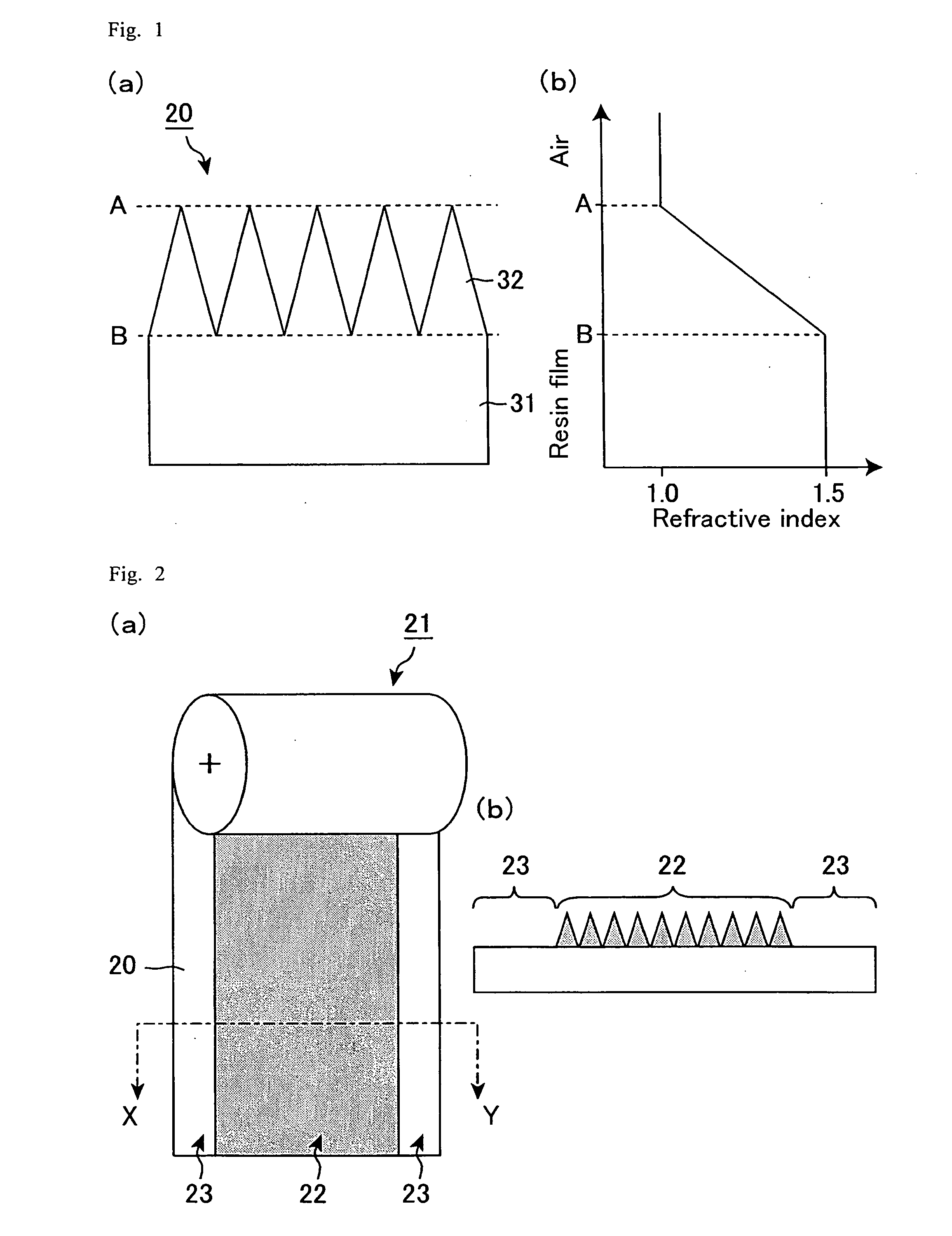
[0047]FIG. 1 is a view illustrating a moth-eye structure (a view illustrating a principle of a continuous change in a refractive index in a surface and a significant decrease in a reflection at an interface). FIG. 1(a) is a cross sectional view schematically showing the moth-eye structure. FIG. 1(b) shows a change in the refractive index in the moth-eye structure.
[0048]For producing nanostructures such as moth-eye structures and wire grid structures, the following nanoimprint is generally used. The nanoimprint includes the steps of pressing an ionizing radiation-curable resin, such as a UV-curable resin, coated on a substrate film (base film) to be sufficiently in contact with a mold for the nanostructures; and irradiating the ionizing radiation-curable resin with energy beams such as UV rays, with the resin being in contact with the mold, thereby curing the resin. The nanostructures formed by the method are nanosized recesses and protrusions formed on a surface of th...
example 1
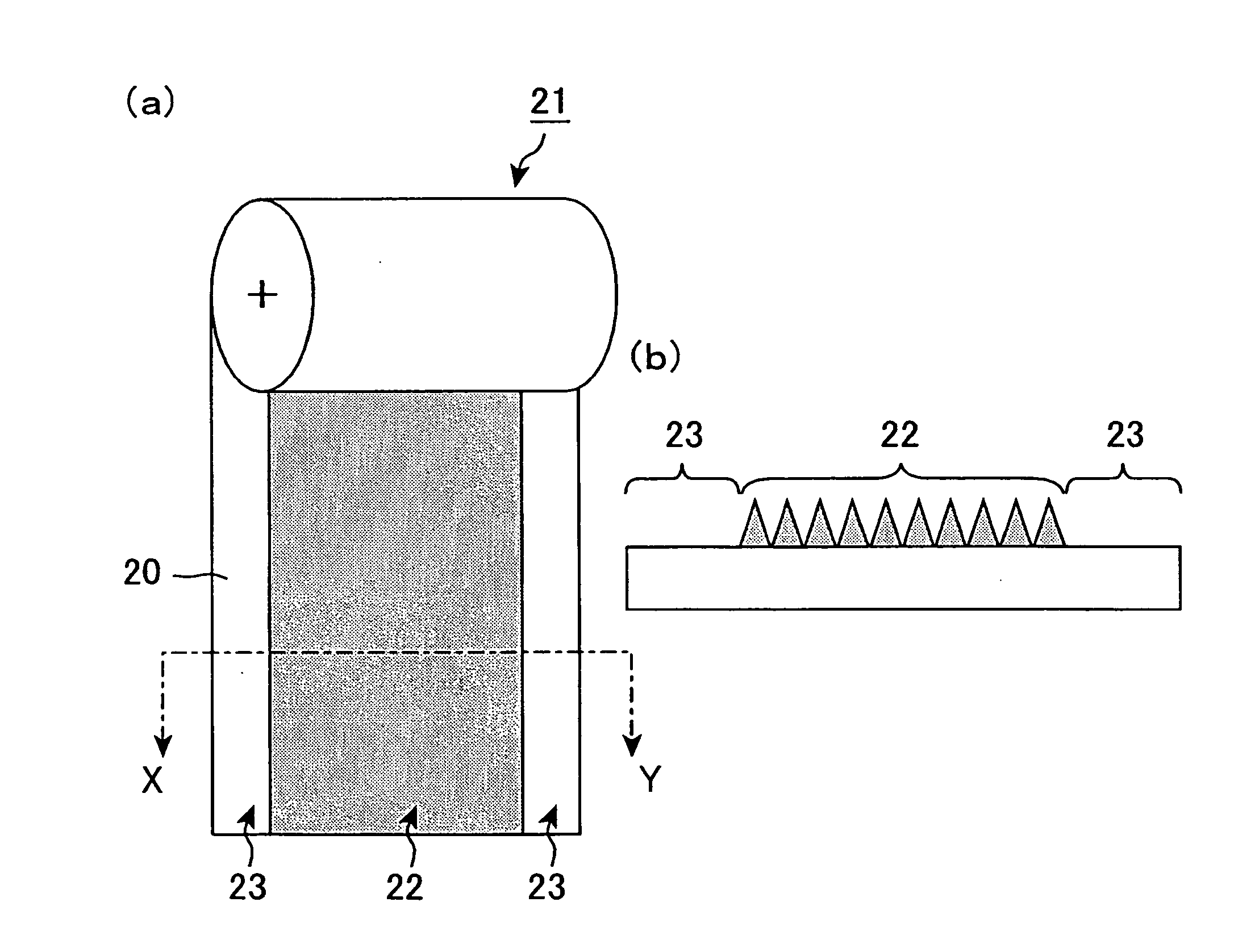
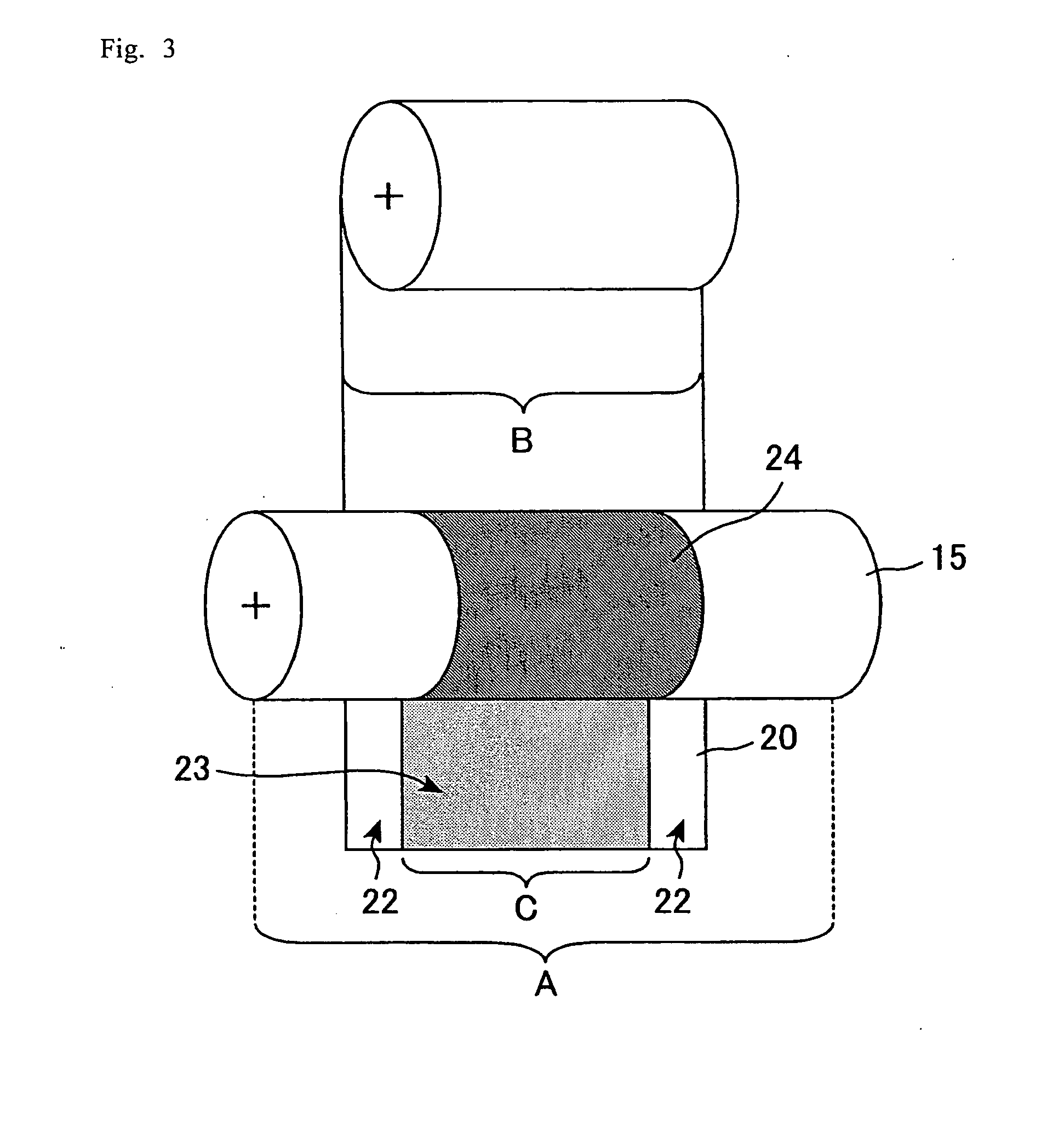
[0080]A mold roller for moth-eye structures was produced by the production method of a mold roller shown in FIG. 4. As shown in FIG. 4, a recess-protrusion pattern having a width of 360 mm was formed in a center portion excluding both ends of the mold roller so that a moth-eye structure-free region with a 20 mm in width can be formed in each of both ends of a base film (nanostructure film) having a width of 400 mm. The mold roller had the roll length of 450 mm, and as the mold roller, a cylindrical body having an outer diameter of 250 mm and an inside diameter of 124 mm is used. The mold roller was then set in the nanoimprinter shown in FIG. 5(b), a UV-curable resin was coated on one surface of a PET film (product of Toray Industries, Inc.) as a base film having a width of 400 mm, and then irradiated with UV rays to cure the UV-curable resin while the PET film was pressed into the mold roller with a pressure of 200 g / cm2. Thus, the nanostructure film was produced. The lamination fil...
example 2
[0081]Similarly to Example 1, a nanostructure film having moth-eye structures was produced, except that the UV-curable resin was coated only on a center portion of the PET film that is used as a base film without being coated on both ends of the PET film. The nanostructure film produced had conical protrusions constituting the moth-eye structures only in a region where the UV-curable resin was coated, and had a region where the base film is exposed in both ends of the nanostructure film. Similarly to Example 1, when the lamination film was attached to the nanostructure film, the lamination film was closely in contact with the exposed base film, thereby fixing the lamination film on the moth-eye structures.
PUM
| Property | Measurement | Unit |
|---|---|---|
| width | aaaaa | aaaaa |
| width | aaaaa | aaaaa |
| width | aaaaa | aaaaa |
Abstract
Description
Claims
Application Information