Method for manufacturing a glass substrate for a magnetic disc

a technology of magnetic discs and glass substrates, which is applied in the manufacture of base layers, edge grinding machines, manufacturing tools, etc., can solve the problems of thermal asperity failure, defective films, and inability to obtain proper glide height, etc., and achieve short processing time, high roundness, and short processing time

Active Publication Date: 2010-11-11
HOYA CORP
View PDF3 Cites 12 Cited by
  • Summary
  • Abstract
  • Description
  • Claims
  • Application Information

AI Technical Summary

Benefits of technology

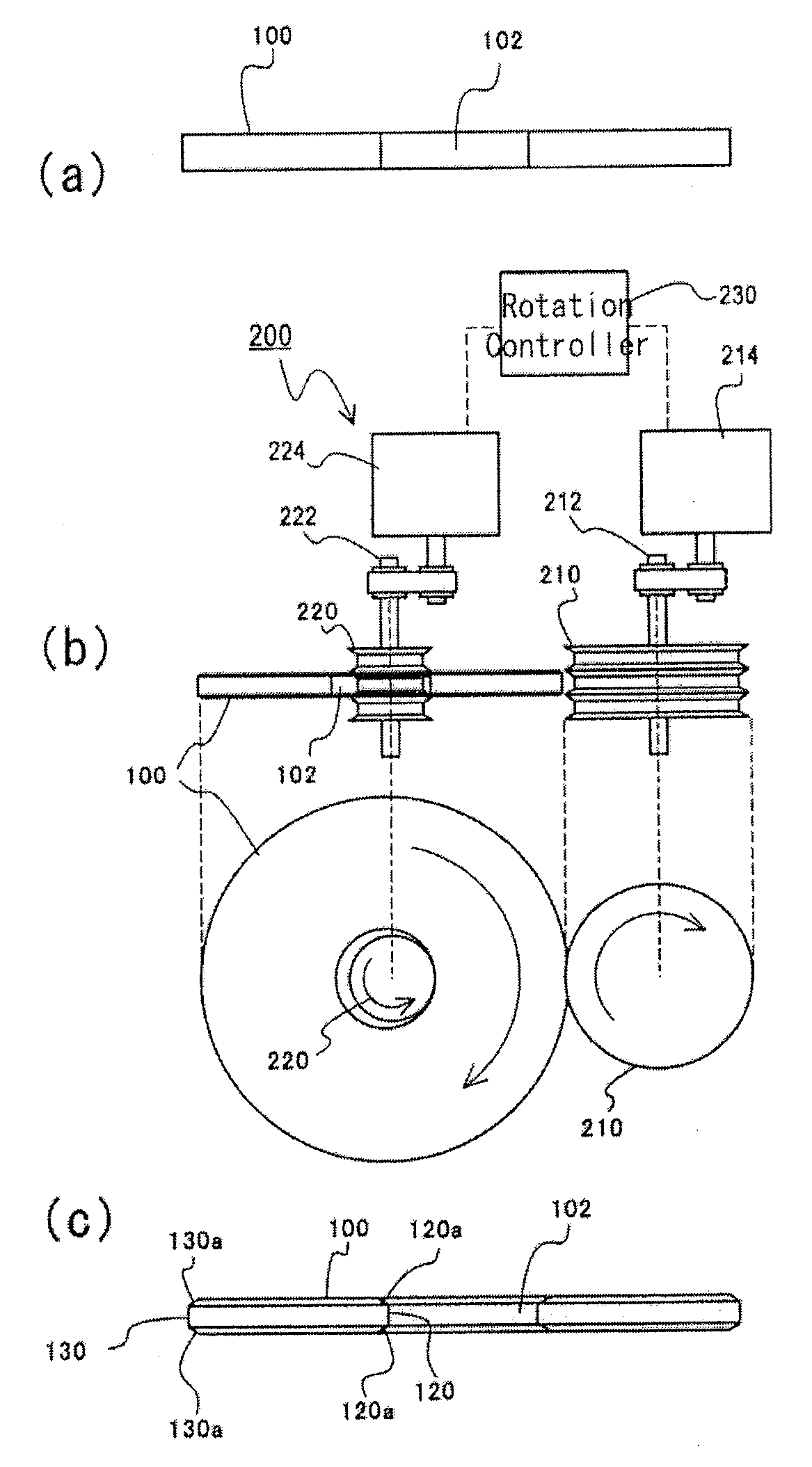
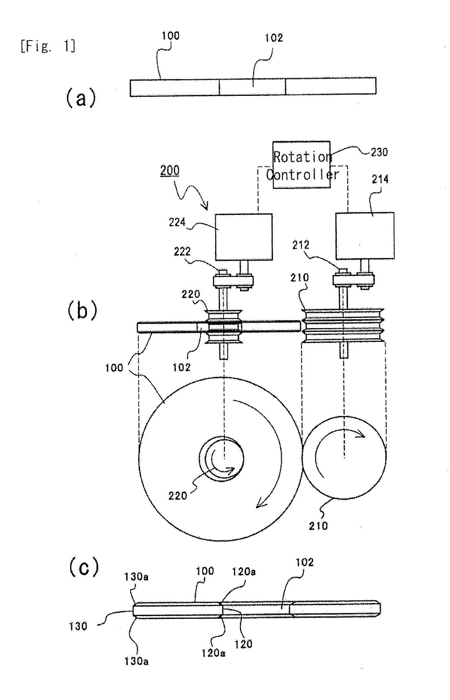
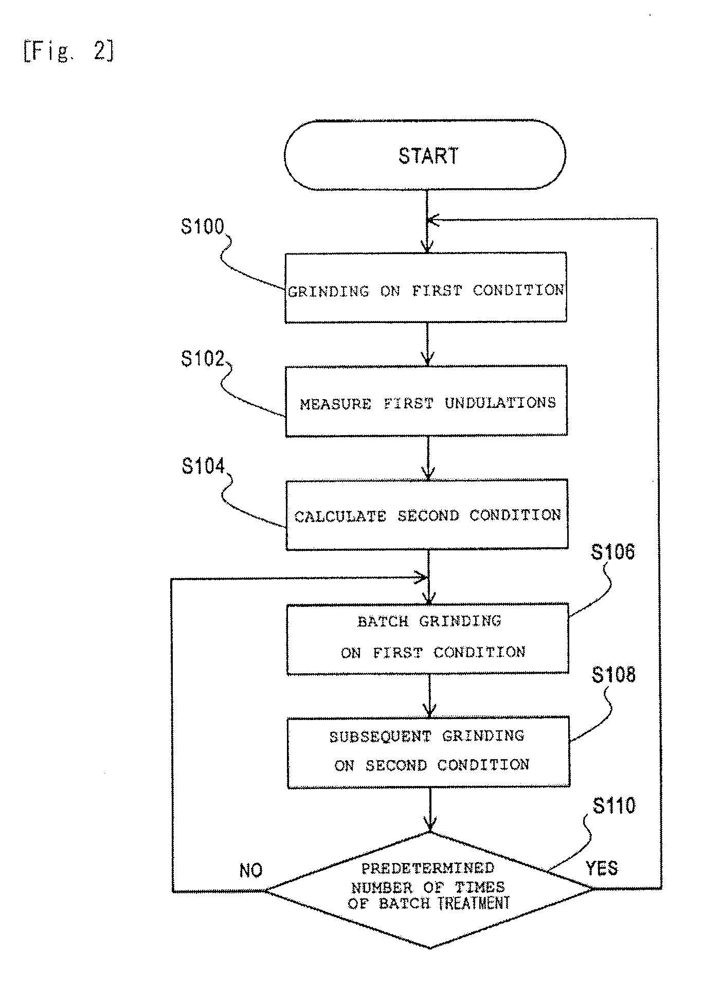
[0023]In the forming step, processing may be performed using the first condition, and processing may be performed after a change to the second condition with the rotating grindstone pressed against the glass substrate. Processing time can be shortened by continuously performing processing in this way. Additionally, when the first condition and the second condition are rotational frequencies, particularly condition changes are continuously enabled.
[0024]In the forming step, the rotational frequency B2 (rpm) of the glass substrate on the second condition may be a rotational frequency at which the value of a first decimal place becomes 5 when the rotational frequency of the rotating grindstone is defined as A (rpm), the rotational frequency of the glass substrate on the first condition is defined as B1 (rpm), the number of undulations is defined as C, and an operation result of (B1 / B2)×C is rounded off to a first decimal place. By setting the second condition in this way, the first undulations which are formed according to the first condition can be out of phase with the second undulations by half, and the first undulations can be surely offset, so that a smooth outer peripheral end face can be obtained.
[0025]According to the invention, it is possible to provide a method for manufacturing a glass substrate for a magnetic disc capable of eliminating undulations of an outer peripheral end face of a glass substrate in a short processing time, and obtaining high roundness. Accordingly, generation of particles can be prevented in a magnetic disc, and generation of corrosion from the outer peripheral end face can be suppressed in the magnetic disc.

Problems solved by technology

If a magnetic layer is formed while the particles have adhered to the main surfaces of the glass substrate, the particles cause film defects, or convex portions are formed in the surface of a magnetic disc.
Thus, proper glide height is not obtained, and a thermal asperity failure is caused.
Additionally, as the ends are chipped, there is a probability that the strength of the glass substrate may deteriorate or the precision of concentricity may deteriorate.
That is, the grinding of the ends of the substrate has been a big issue in order to reduce the rate of occurrence of chipping, improve production efficiency, and reduce manufacturing cost.
However, since a magnetic head does not run on the outer peripheral end face and the outer peripheral end face was also mirror-polished, this was not conventionally acknowledged as a problem.
Such damage causes generation of particles, and consequently, if the generated particles are attracted to the main surfaces, they cause convex defects after a magnetic disc is obtained, and cause a thermal asperity failure or a head crash.
Additionally, metal ion included in the glass substrate is apt to be eluted from such damaged spots, and this causes corrosion which precipitates on the surface of the magnetic disc.
These problems are big problems with a further increase in capacity and a further increase in recording density in future.
However, since it is necessary to produce glass substrates on a large scale inexpensively, it is difficult to secure enough processing time to eliminate the undulations.

Method used


Image

  • Method for manufacturing a glass substrate for a magnetic disc
  • Method for manufacturing a glass substrate for a magnetic disc
  • Method for manufacturing a glass substrate for a magnetic disc

Examples


working example

[0076]Hereinafter, an embodiment will be described below about a method for manufacturing a glass substrate for a magnetic disc to which the invention is applied.

(1) Shaping Step And First Lapping Step

[0077]Although materials for a glass substrate in this embodiment include soda lime glass, aluminosilicate glass, borosilicate glass, crystallized glass, etc., aluminosilicate glass is especially suitable. Since smoothness and high rigidity are obtained in the aluminosilicate glass, magnetic spacing, especially the floating height of a magnetic head can be reduced more stably. Additionally, in the aluminosilicate glass, high rigidity and strength can be obtained by chemical strengthening.

[0078]First, melted aluminosilicate glass was molded into a disc shape by direct pressing using an upper mold, a lower mold, and a barrel mold, and amorphous plate-like glass was obtained. In addition, glass for chemical strengthening was used as the aluminosilicate glass. A disc-like glass substrate f...


PUM

PropertyMeasurementUnit
floating heightaaaaaaaaaa
timeaaaaaaaaaa
Raaaaaaaaaaa

Abstract

The invention aims at providing a method for manufacturing a glass substrate for a magnetic disc capable of eliminating undulations of an outer peripheral end face of a glass substrate in a short processing time, and obtaining high roundness. In a method for manufacturing a disc-like glass substrate for a magnetic disc, the method includes a forming step of pressing a rotating grindstone against an outer peripheral end face while the glass substrate is rotated, thereby forming an outer peripheral end. In the forming step, processing is performed using a first condition (S106) on which first undulations are formed and a second condition (S108) on which second undulations having a different wavelength from the first undulations are formed.

Description

BACKGROUND OF THE INVENTION[0001]1. Field of the Invention[0002]The present invention relates to a method for manufacturing a glass substrate for a magnetic disc to be used as a recording medium of a computer or the like.[0003]2. Description of the Related Art[0004]In recent years, an information recording technique, especially a magnetic recording technique is remarkably progressing with advancement of an information technique. As substrates for magnetic recording media such as HDDs (hard disk drives) that is one of magnetic recording media, a glass substrate which can be made small and thin and made high in recording density as compared to an aluminum substrate which is used conventionally and which is excellent regarding the flatness and substrate strength of the surface of the substrate is adopted.[0005]Additionally, in order to achieve high recording density in a magnetic disc to be used for HDDs or the like, a vertical magnetic recording type magnetic disc (vertical magnetic r...

Claims


Application Information

Patent Timeline
Patent Type & Authority Applications(United States)
IPC IPC(8): B24B9/08B24B1/00
CPCB24B5/04G11B5/8404B24B9/065
Inventor UEDA, MASAAKIKASHIMA, RYUICHISAKAGUCHI, SEIJI
Owner HOYA CORP
Why Eureka
Try Eureka