Supercharge Your Innovation With Domain-Expert AI Agents!

Laser Scalpel

Inactive Publication Date: 2010-11-11
A R C LASER
View PDF5 Cites 4 Cited by
  • Summary
  • Abstract
  • Description
  • Claims
  • Application Information

AI Technical Summary

Benefits of technology

[0008]According to one implementation, the laser light (or the laser beam) may be coupled into the scalpel body at an acute angle, selected from an angular range of between 15° and 55°, with respect to the surface normal (or axis of incidence) of the coupling-in surface, that is to say with respect to the direction or axis perpendicular or normal to the coupling-in surface, unlike the prior art, where there is perpendicular incidence. The e

Problems solved by technology

The concave or convex design of the reflection surface as per FIG. 10a likewise means increased complexity when polishing the crystal.

Method used


Image

  • Laser Scalpel
  • Laser Scalpel
  • Laser Scalpel

Examples


Embodiment Construction

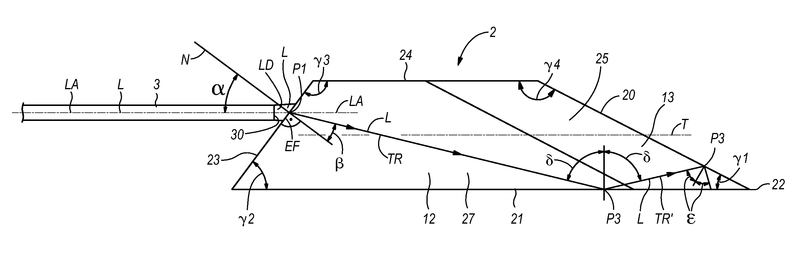
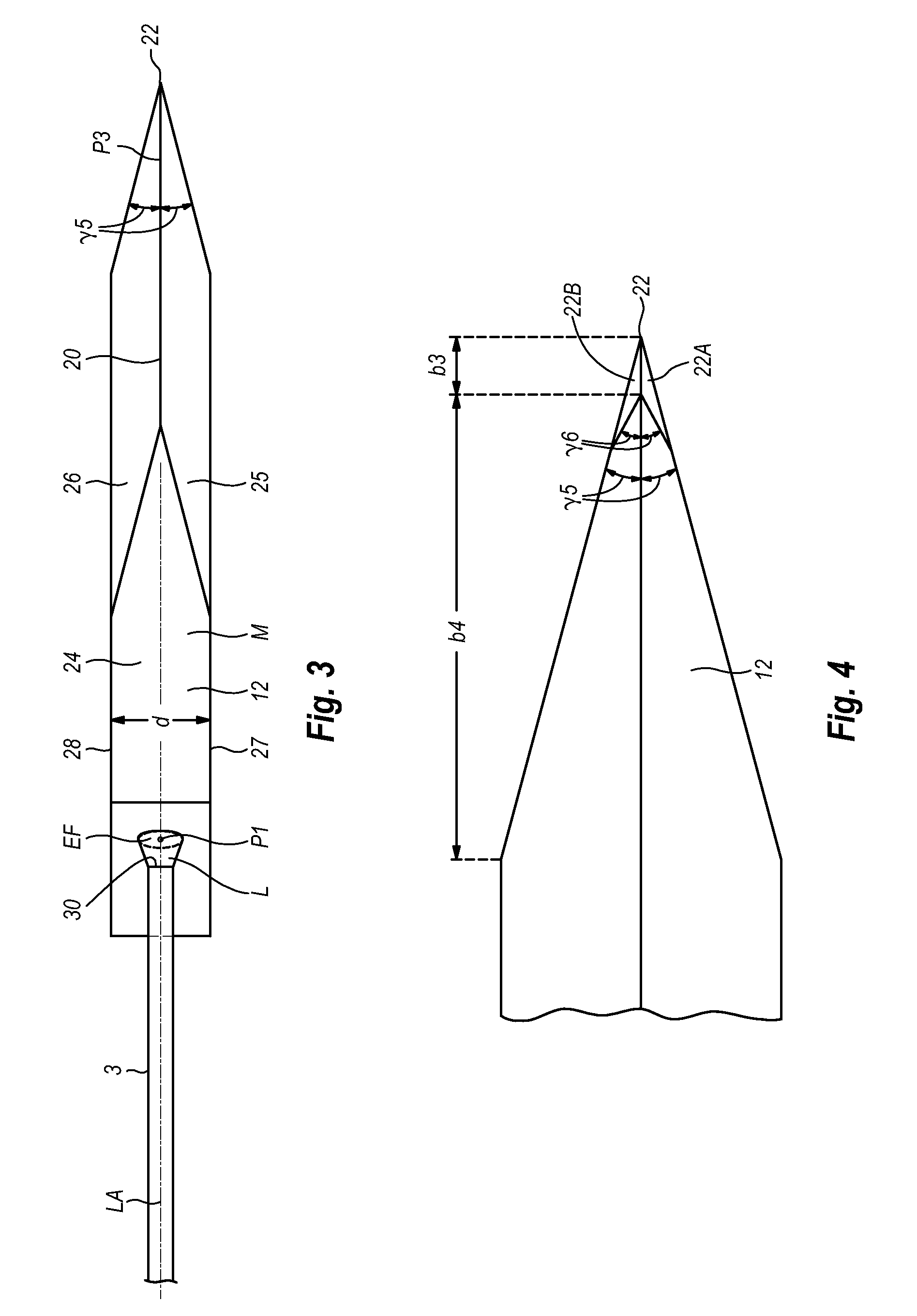
[0016]The laser scalpel (or laser blade, laser knife) 2 as per FIGS. 1 to 3 comprises a scalpel body 12 and an optical waveguide 3, in particular an optical fiber, for coupling laser light (or laser radiation, a laser beam) L from a laser source (not illustrated) into the scalpel body 12.

[0017]The scalpel body 12 is basically designed as an irregular polyhedron with a plurality of planar or flat polyhedral surfaces (or flat sides, outer surfaces, bevels), which together form common edges and delimit the scalpel body 12 toward the outside. A scalpel back 21, a rear side 23, a base surface 24, two side surfaces 27 and 28, and finally two cutting surface 25 and 26, which converge on a cutting edge 20, are provided as polyhedral sides of the scalpel body 12. The scalpel body 12 has a mirror-symmetrical design in respect of a central plane M. The base surface 24 and the scalpel back 21 run parallel to one another at a constant distance, which defines the height h of the scalpel body 12.

[...


PUM


Abstract

The invention is based on the object of specifying a laser scalpel, by means of which a high proportion of the laser light coupled into the scalpel body can be provided on the scalpel edge or is able to emerge therefrom. According to a first aspect, the invention is based on the idea of coupling the laser light into the scalpel body at an acute angle, with respect to the surface normal of the coupling-in surface, that is to say with respect to the direction or axis perpendicular or normal to the coupling-in surface.

Description

BACKGROUND OF THE INVENTION[0001]1. Technical Field[0002]The invention relates to a laser scalpel.[0003]2. Background and Relevant Art[0004]WO 01 / 87176 A1 has disclosed a surgical laser scalpel with a scalpel body made of a diamond crystal, the body of which having, on the one hand, a polished scalpel blade and polished outer surfaces and, on the other hand, a laser, the laser light of which is introduced into the scalpel body via an optical fiber and predominately re-emerges from the scalpel body in the region of the scalpel blade. The emerging laser radiation in the region of the scalpel blade causes photocoagulation of the blood and thus reduces the bleeding of the wound.[0005]In an embodiment described in FIGS. 10a and 10b, the laser axis of the optical waveguide at a coupling-in surface on a flat crystal outer surface is perpendicular to the corresponding crystal outer surface, hence the laser beam is incident on the scalpel body in a perpendicular fashion and, furthermore, the...

Claims


Application Information

Patent Timeline
IPC IPC(8): A61B18/20
CPCA61B17/3211A61B18/22A61B2019/5206A61B2018/2261A61B2018/2266A61B18/24A61B2090/306A61B2018/00589
Inventor WALKER, RUDOLFVOLLAND, GERDTHYZEL, REINHARDT
Owner A R C LASER
Features
  • R&D
  • Intellectual Property
  • Life Sciences
  • Materials
  • Tech Scout
  • Unparalleled Data Quality
  • Higher Quality Content
  • 60% Fewer Hallucinations
Learn More