
Method and system for testing safety automation logic of a manufacturing cell

a manufacturing cell and automation logic technology, applied in the direction of ignition automatic control, electric controllers, instruments, etc., can solve the problems of affecting the safety the inability to completely test the various safety features of the manufacturing cell, and the inability to fully test the various safety features

Inactive Publication Date: 2010-11-11
GM GLOBAL TECH OPERATIONS LLC
View PDF12 Cites 17 Cited by
  • Summary
  • Abstract
  • Description
  • Claims
  • Application Information

AI Technical Summary

Benefits of technology

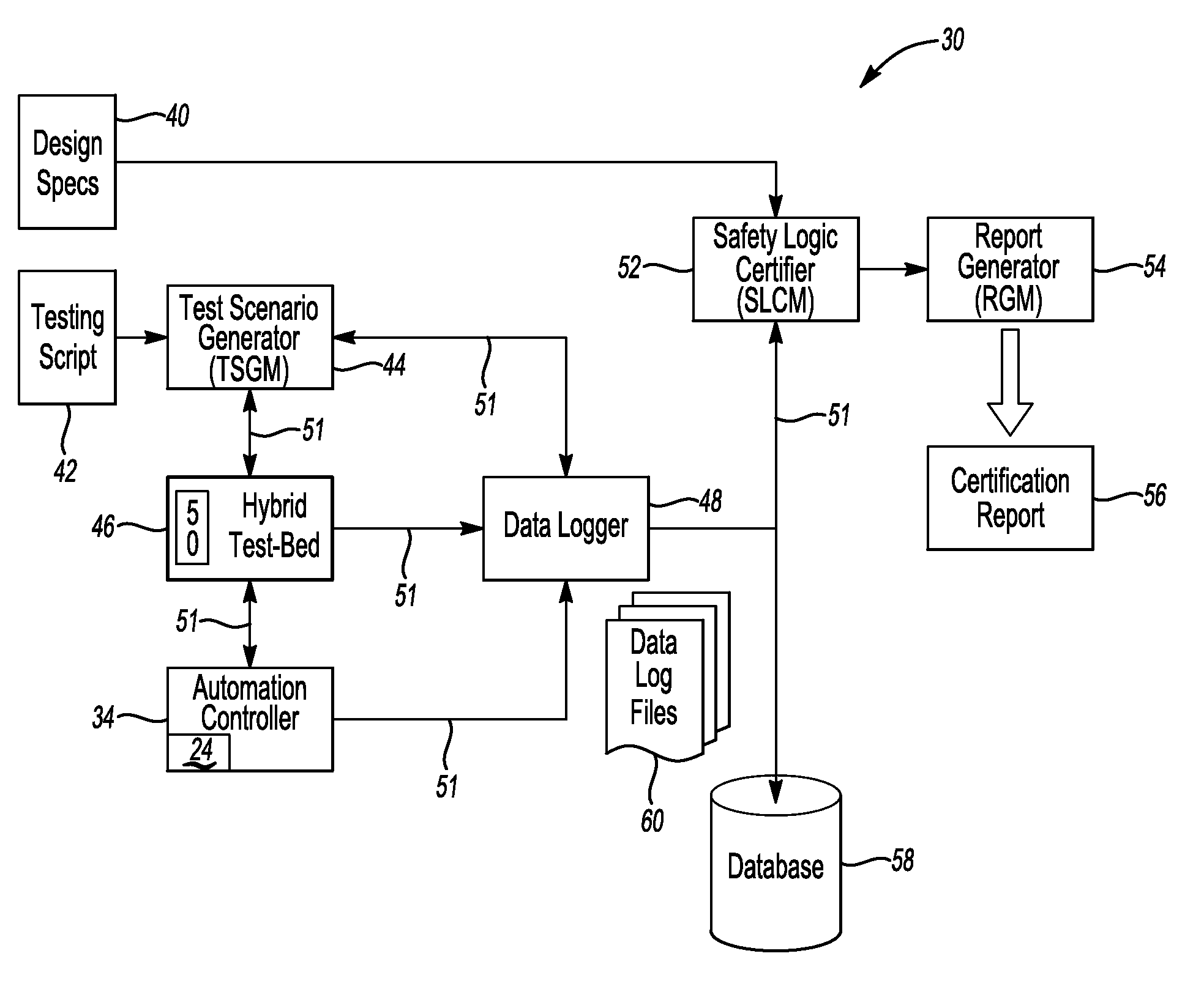
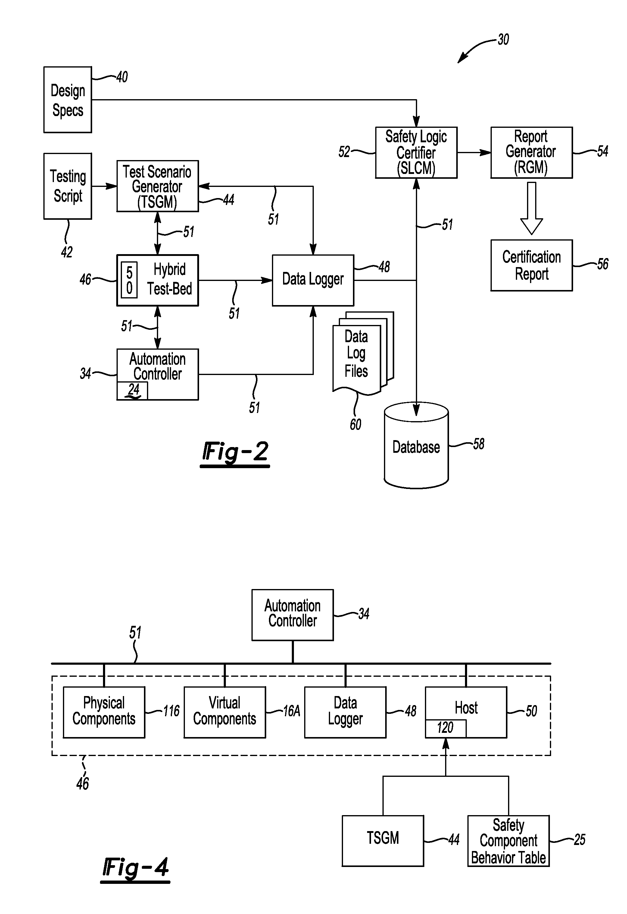
The present invention provides a method and system for testing the safety automation logic used in the operational control of a manufacturing cell. This hybrid approach integrates hardware and software solutions to test the safety automation logic of a safety-related component used in the cell, as well as the overall safety automation logic of the cell. The system includes a host machine, safety-related component, and additional components set up in a test bed environment. The testing scenario generator module generates input control signals based on predetermined test scenarios, and the recorded behavior of the safety-related component is played back on the automation controller to electronically emulate its operation. The performance of the safety automation logic is then certified using the test signals. The technical effects of this invention include improved safety and reliability in manufacturing processes, as well as efficient and effective testing of safety automation logic.

Problems solved by technology

Attempted access into the working area of the cell can be instantly detected using such sensors, resulting in an almost instantaneous shut down or suspension of operation of automated running equipment in the cell if access is attempted.
Conventional logic certification and testing methods utilize purely hardware-based testing, and may result in a longer setup time and relatively high testing costs.
Additionally, such methods may not provide a viable method for completely testing the various safety-related tasks and concerns of a cell.
For example, some operator-triggered events, such as the interruption of a perimeter light curtain with a nearly simultaneous activation of an E-Stop device located a substantial distance away from the light curtain, may be difficult to achieve in a reliable and highly repeatable manner.
Also, safety-related components and sensors may be provided in black-box form from a supplier, thereby making the complete testing of components and their overall system a challenging task.

Method used


Image

  • Method and system for testing safety automation logic of a manufacturing cell
  • Method and system for testing safety automation logic of a manufacturing cell
  • Method and system for testing safety automation logic of a manufacturing cell

Examples


Embodiment Construction

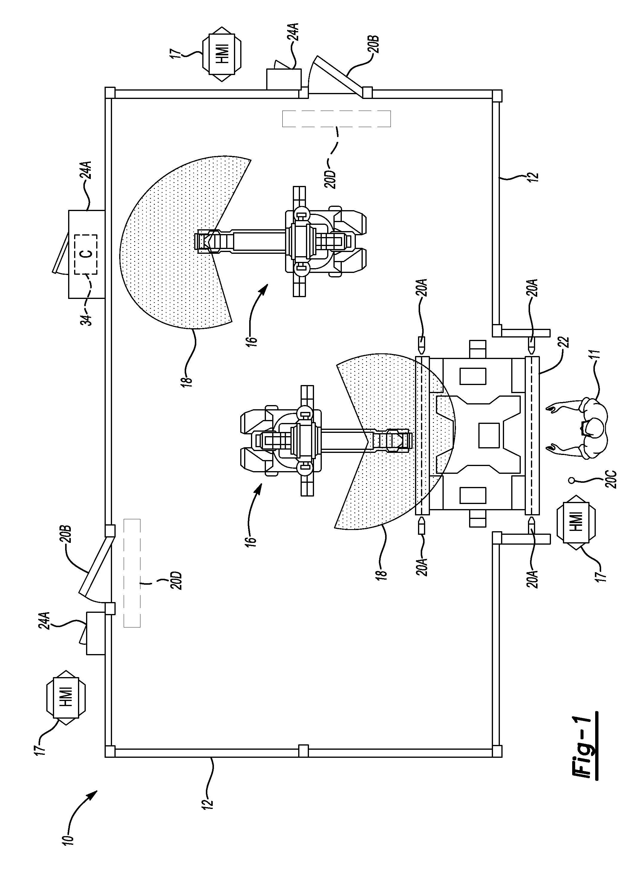
[0018]Referring to the drawings, wherein like reference numbers correspond to like or similar components throughout the several figures, and beginning with FIG. 1, a manufacturing cell 10 may include various normal task-related components and safety-task related components for manufacturing and / or assembly of a product, as well as for ensuring that the cell 10 and its perimeter fence 12 are sufficiently monitored for the presence of operators 11 as described below.

[0019]Normal task-related components of the cell 10 may include, but are not necessarily limited to, robots 16 adapted for performing one or more work-related tasks. To perform such work-related tasks, each robot 16 may automatically move within a predetermined operating zone 18, with each operating zone 18 representing the effective range of motion of the robots 16. Safety task-related components of the cell 10 may include, by way of example, a light emitter / receiver 20A configured for generating and receiving a light bea...


PUM


Abstract

A method for testing the safety automation logic used in a manufacturing cell includes recording control signals of a safety-related component such as an E-Stop, light curtain, gate lock, or a safety mat using a host machine, and then disconnecting the component from the host machine. The recorded test signals are transmitted to an automation controller in accordance with a test scenario from a test scenario generator module (TSGM) to emulate operation of the component. The automation logic may be certified using the playback of the recorded test signals. A system for testing the safety automation logic includes the controller, host machine, and TSGM. The host machine records the control signals and plays back the test signals on the controller to emulate operation of the component. The automation control logic may be certified using the test signals, e.g., by comparing these to the test specification or standard.

Description

TECHNICAL FIELD[0001]The invention relates generally to the testing of automation logic, and in particular to a computer-executable method and system for testing the safety-related automation logic that is used in a manufacturing cell.BACKGROUND OF THE INVENTION[0002]Various processes and robotic equipment may be used to facilitate product manufacturing and assembly, such as but not limited to products such as vehicles or onboard systems. Automated manufacturing cells may be laid out on a plant floor to streamline production. To ensure plant floor safety, the perimeter of a given cell is typically closely monitored and access thereto is guarded using fences and various safety sensors and components, e.g., push-button or E-Stop devices, light curtains, safety mats, laser scanners, guard locks, safety rope, etc. Attempted access into the working area of the cell can be instantly detected using such sensors, resulting in an almost instantaneous shut down or suspension of operation of a...

Claims


Application Information

Patent Timeline
Patent Type & Authority Applications(United States)
IPC IPC(8): G05B9/02G06F11/00G06G7/66
CPCG06F11/261G05B9/02
Inventor LIU, JINGYUAN, CHENGYINGU, FANGMINGBILLER, STEPHAN R.WOOD, DEMET C.AUFDERHEIDE, DANIEL B.
Owner GM GLOBAL TECH OPERATIONS LLC
Learn More