Directional resistivity imaging using harmonic representations

a technology of directional resistivity and harmonic representation, which is applied in the field of forming directional resistivity images of subterranean boreholes, to achieve the effects of superior noise rejection, reduced signal noise, and misleading interpretation of respons

Active Publication Date: 2010-11-11
SCHLUMBERGER TECH CORP
View PDF50 Cites 45 Cited by
  • Summary
  • Abstract
  • Description
  • Claims
  • Application Information

AI Technical Summary

Benefits of technology

[0010]Exemplary embodiments of the present invention may advantageously provide several technical advantages. For example, the harmonic representation methodology of the present invention tends to provide a more accurate representation of the true directional resistivity signal (which is typically sinusoidal in azimuth) than does conventional binning. This is especially the case when a small number of azimuthal sectors (or bins) are utilized. As such, the invention tends to be advantageous in borehole imaging applications utilizing a small number of azimuthal sectors (such as applications in which the data (image) is transmitted to the surface in substantially real time during drilling).
[0011]Moreover, the present invention essentially stacks all of the available data points made at a particular measured depth (or in a predetermined time interval) in computing the first order harmonic representation for each azimuthal sector. The invention therefore tends to provide superior noise rejection as compared to prior art binning techniques. The invention further reduces signal noise by removing (mathematically filtering out) higher order harmonics (which are commonly related to signal noise).

Problems solved by technology

Such DC bias is commonly the result of drifting downhole electronics (e.g., due to temperature and pressure change during drilling).

Method used


Image

  • Directional resistivity imaging using harmonic representations
  • Directional resistivity imaging using harmonic representations
  • Directional resistivity imaging using harmonic representations

Examples


Embodiment Construction

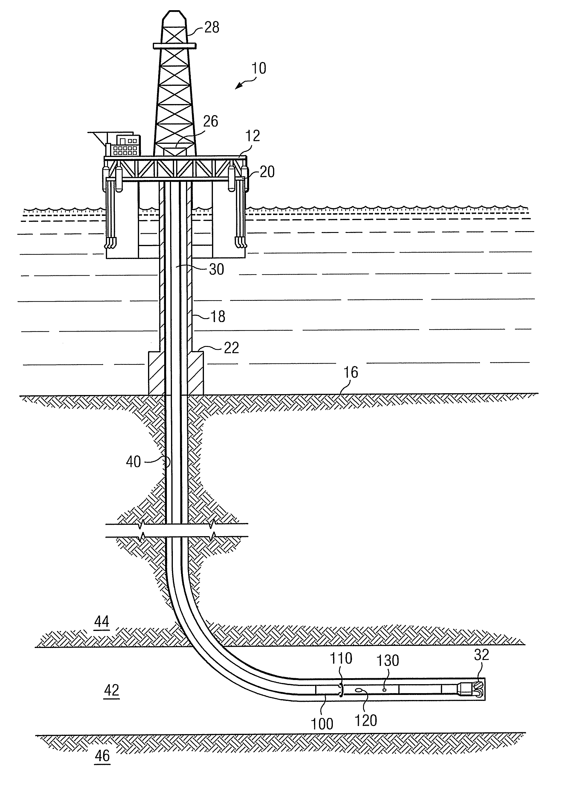
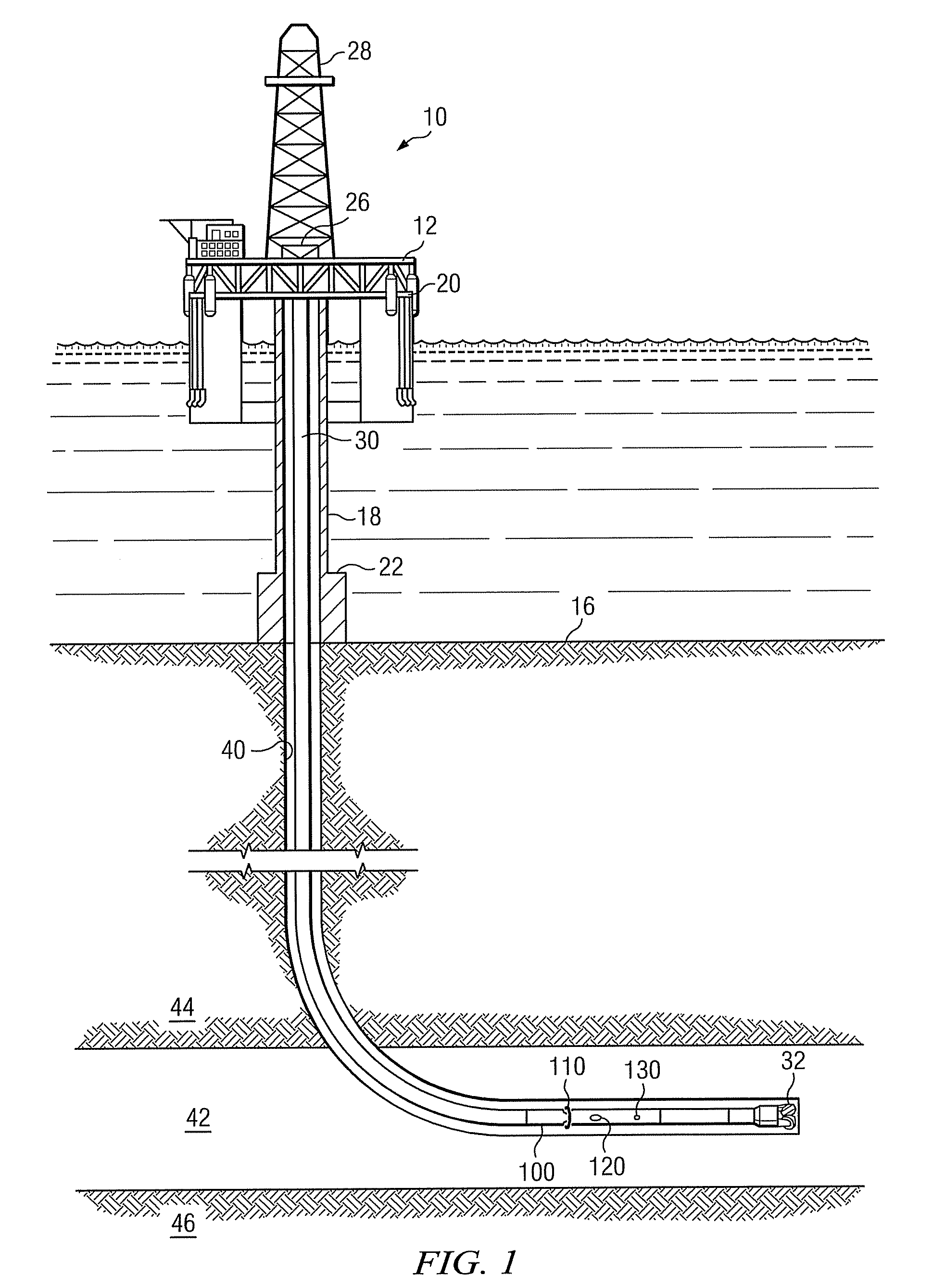
[0020]FIG. 1 schematically illustrates one exemplary embodiment of a logging while drilling directional resistivity tool 100 suitable for use with the present invention in an offshore oil or gas drilling assembly, generally denoted 10. In FIG. 1, a semisubmersible drilling platform 12 is positioned over an oil or gas formation (not shown) disposed below the sea floor 16. A subsea conduit 18 extends from deck 20 of platform 12 to a wellhead installation 22. The platform may include a derrick 26 and a hoisting apparatus 28 for raising and lowering the drill string 30, which, as shown, extends into borehole 40 and includes a drill bit 32 and LWD directional resistivity tool 100. Resistivity tool 100 typically includes at least one transmitting antenna 110 and at least one receiving antenna 120. The tool may further include an azimuth sensor 130 deployed thereon.

[0021]Azimuth sensor 130 (also referred to in the art as an orientation sensor) may include substantially any sensor that is s...


PUM


Abstract

A method for making directional resistivity measurements and forming a directional resistivity image of a subterranean formation includes processing a plurality of directional resistivity measurements and corresponding azimuth angles to calculate a first order harmonic representation at selected azimuth angles. A two dimensional borehole image may be formed by repeating the procedure at multiple measured depths in the borehole.

Description

RELATED APPLICATIONS[0001]None.FIELD OF THE INVENTION[0002]The present invention relates generally to a method for forming directional resistivity images of a subterranean borehole. More specifically, this invention relates to processing directional resistivity data to obtain first order harmonic representations at selected azimuth angles to form a directional resistivity image of the subterranean formation.BACKGROUND OF THE INVENTION[0003]The use of electrical measurements in prior art downhole applications, such as logging while drilling (LWD), measurement while drilling (MWD), and wireline logging applications is well known. Such techniques are commonly utilized to determine a subterranean formation resistivity, which, along with formation porosity measurements, may be used to indicate the presence of hydrocarbons in the formation. For example, it is known in the art that porous formations having a high electrical resistivity often contain hydrocarbons, such as crude oil, while p...

Claims


Application Information

Patent Timeline
Patent Type & Authority Applications(United States)
IPC IPC(8): E21B47/04
CPCG01V3/20
Inventor WANG, TSILI
Owner SCHLUMBERGER TECH CORP
Why Eureka
Try Eureka