Processes For The Recovery Of High Purity Hydrogen And High Purity Carbon Dioxide

a technology of high-purity hydrogen and carbon dioxide, which is applied in the field of high-purity hydrogen and high-purity carbon dioxide recovery, can solve the problems of high energy and maintenance costs, large investment required in the recovery process, and high process operation costs

Active Publication Date: 2010-11-18
AIR LIQUIDE IND US LP +1
View PDF23 Cites 38 Cited by
  • Summary
  • Abstract
  • Description
  • Claims
  • Application Information

AI Technical Summary

Problems solved by technology

Accordingly, the processes utilized for this recovery require a large investment due to equipment costs and also high regeneration energy requirements.
The process requires operation at high pressure and cold temperature though.
Therefore, while it may be appropriate to use the CO2 CPU process in a very large scale CO2 recovery plant (>1000 TPD), when applying the CO2 CPU process in a small size CO2 recovery plant (typically 100 to 500 TPD merchant CO2 plants), the energy and maintenance costs are considered to be usually high.

Method used


Image

  • Processes For The Recovery Of High Purity Hydrogen And High Purity Carbon Dioxide
  • Processes For The Recovery Of High Purity Hydrogen And High Purity Carbon Dioxide
  • Processes For The Recovery Of High Purity Hydrogen And High Purity Carbon Dioxide

Examples


first embodiment

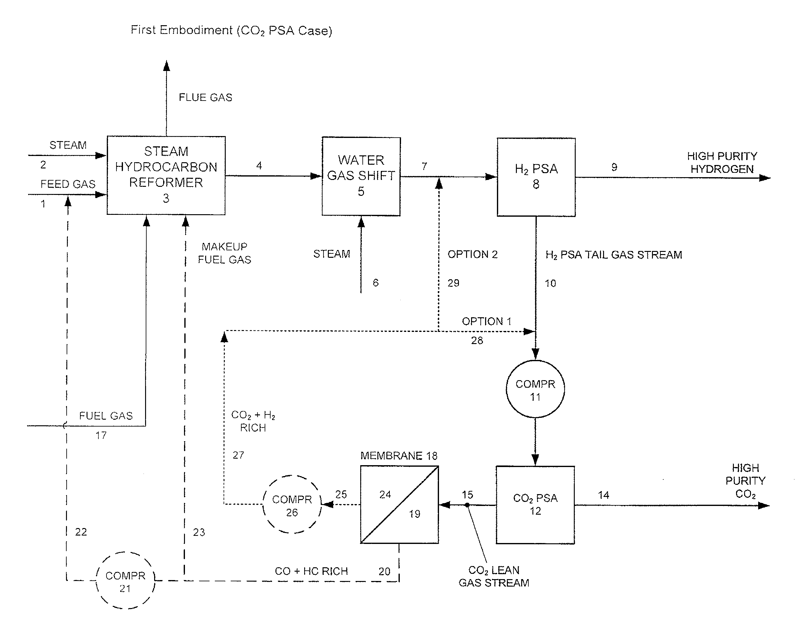
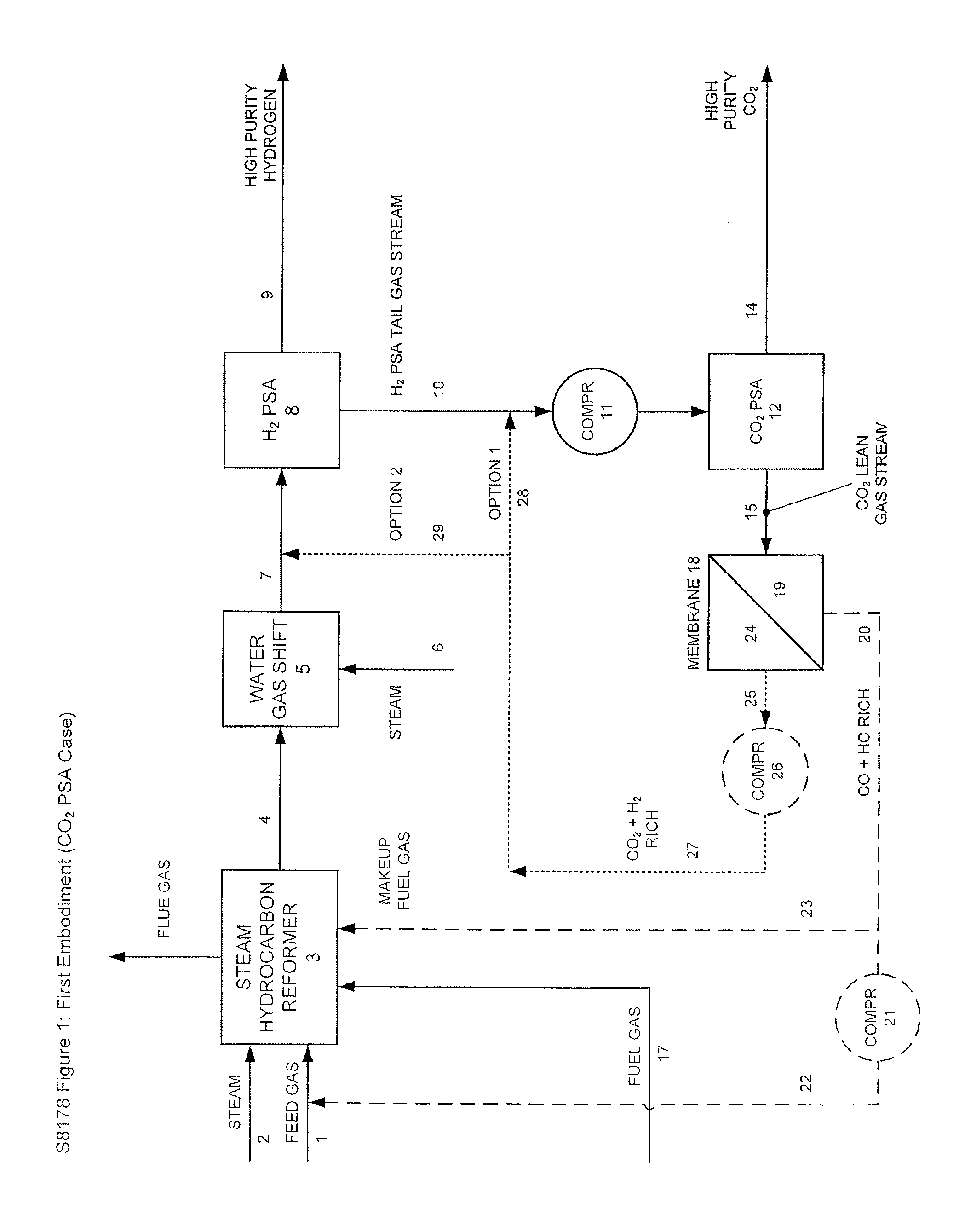
[0017]In the present invention as shown in FIG. 1 and FIG. 2, rather than use the H2 PSA tail gas stream as a makeup fuel, the H2 PSA tail gas stream is instead treated in order to remove the valuable CO2 present as a high purity CO2 stream. This treatment of the H2 PSA tail gas stream is carried out in the present invention using a CO2 PSA unit 12 in combination with a membrane separation unit 18. As used herein, the phrase “CO2 PSA unit” refers to a standard pressure swing adsorption unit in which the various adsorbent beds utilized include an adsorbent that is specific for CO2 in order to allow for the selection and subsequent removal of CO2 from the gas stream being introduced into the CO2 PSA unit 12. More specifically, the PSA unit utilized as the CO2 PSA unit 12 can include any standard PSA unit such as the PSA unit utilized for hydrogen recovery as discussed hereinbefore. The difference between the CO2 PSA unit 12 and the H2 PSA unit 8 is that in the case of the CO2 PSA unit...

second embodiment

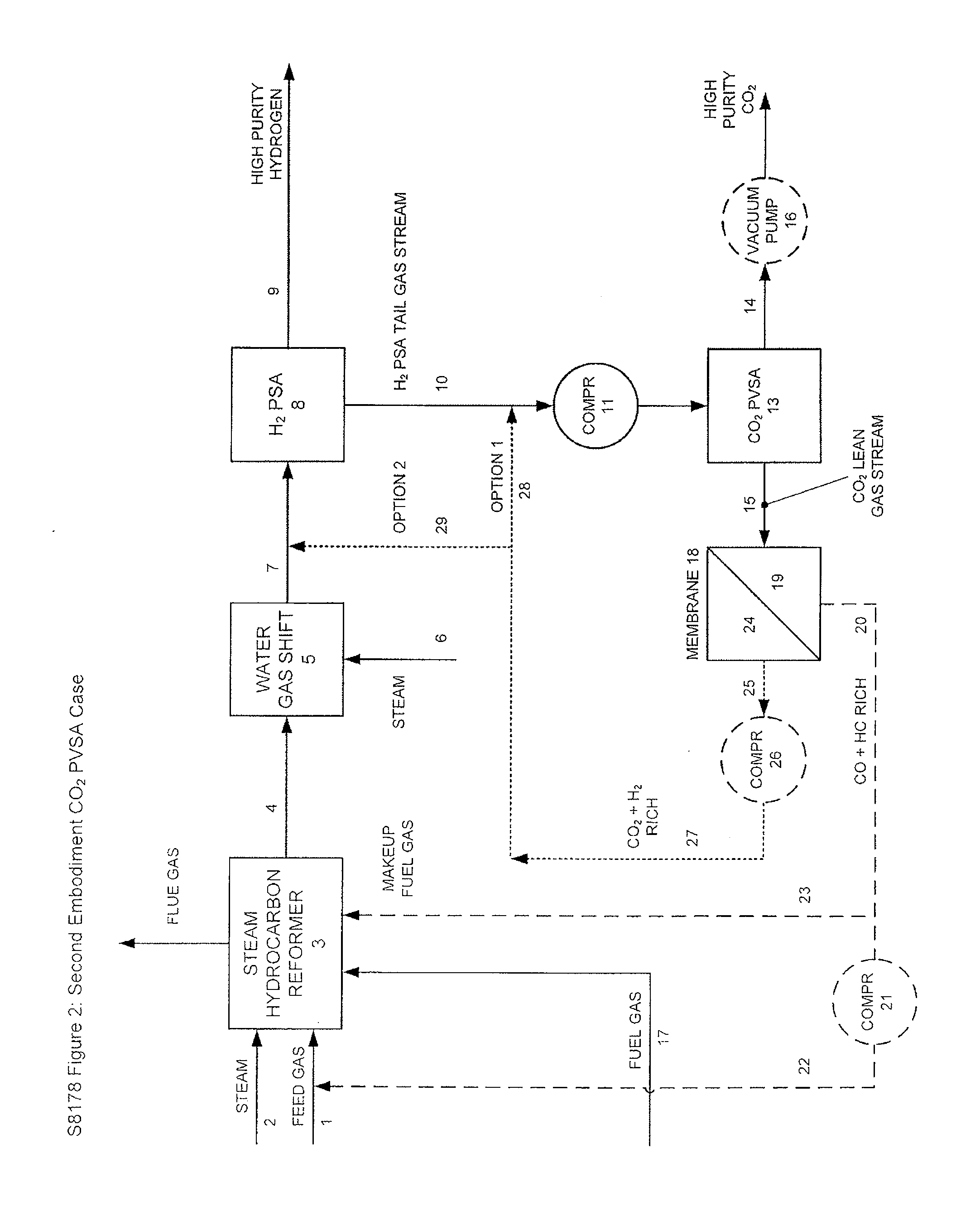
[0018]In the present invention, this treatment is carried out using a CO2 PVSA unit in combination with a membrane separation unit. As used herein with regard to the present invention, the term “PVSA” refers to a non-cryogenic gas separation technology which utilizes the use of adsorbents for the removal of certain gases from a gas mixture and vacuum for the removal of the certain gases from the adsorbents. Furthermore, as used herein, the phrase “CO2 PVSA unit” refers to a pressure vacuum swing unit in which vacuum is used along with an adsorbent that is specific to CO2 in order to select for CO2 removal from a gas stream. Those of ordinary skill in the art will recognize that while it is critical that the PVSA unit be utilized in the process of the present invention, the actual configuration of the PVSA unit is not necessarily critical provided that the PVSA unit comprises two or more static beds of the zeolite adsorbent (also referred to as zeolite beds), preferably from two to f...


PUM

PropertyMeasurementUnit
pressureaaaaaaaaaa
temperaturesaaaaaaaaaa
temperatureaaaaaaaaaa

Abstract

The present invention provides for various processes for recovering high purity gaseous hydrogen and high purity gaseous carbon dioxide from the gas stream produced using steam hydrocarbon reforming, especially steam methane reforming, utilizing a H2 pressure swing adsorption unit in combination with either a CO2 pressure swing adsorption unit in combination with a membrane separation unit or a CO2 pressure vacuum swing adsorption unit in combination with a membrane separation unit. The present invention further relates to a process for optimizing the recovery of carbon dioxide from waste gas streams produced during the hydrogen purification step of a steam hydrocarbon reforming / water gas shift reactor / H2 pressure swing adsorption unit utilizing either a CO2 pressure swing adsorption unit in combination with a membrane separation unit or a CO2 pressure vacuum swing adsorption unit in combination with a membrane separation unit. The present invention even further relates to the apparatus necessary to carry out the various processes of the present invention.

Description

[0001]The present invention claims priority from U.S. Provisional Patent Application Ser. No. 61 / 179,225, entitled “Processes For The Recovery of High Purity Hydrogen and High Purity Carbon Dioxide” filed May 18, 2009.FIELD OF THE INVENTION[0002]The present invention relates to various processes for recovering high purity carbon dioxide from waste gas streams produced during the hydrogen purification step of a steam hydrocarbon reforming unit / water gas shift reactor / H2 pressure swing adsorption unit process.BACKGROUND[0003]Interest in the recovery of carbon dioxide (hereinafter “CO2”) from various CO2 containing gas mixtures has increased due to a variety of factors including the merchant CO2 market, enhanced oil recovery (hereinafter “EOR”) and greenhouse gas emissions reduction. The currently available systems for recovering high purity CO2 use a variety of generic and proprietary physical and chemical solvents. Accordingly, the processes utilized for this recovery require a large...

Claims


Application Information

Patent Timeline
Patent Type & Authority Applications(United States)
IPC IPC(8): F25J3/00C01B32/50
CPCC01B3/384Y02C10/08C01B3/501C01B3/56C01B2203/0233C01B2203/0283C01B2203/0405C01B2203/043C01B2203/047C01B2203/0475C01B2203/048C01B2203/0495C01B2203/1058C01B2203/1241C01B2203/146C01B2203/148C01B3/48Y02C20/40
Inventor CHEN, YUDONGFAIR, GLENN
Owner AIR LIQUIDE IND US LP
Why Eureka
Try Eureka