Sampling apparatus and method for sampling

Active Publication Date: 2010-11-18
SOURCE TECH INC
View PDF4 Cites 9 Cited by
  • Summary
  • Abstract
  • Description
  • Claims
  • Application Information

AI Technical Summary

Benefits of technology

[0018]It is thus a sampling cup where the product is not emptied by the same opening through which it is filled. Therefore, an apparatus according to the invention may be designed in a simple and reliable way as it is not necessary to perform a turning movement of the sampling cup in order to empty it.
[0034]A further advantage of measuring the “compacted” density in connection with a sampling cup is that simultaneously a water measurement of the sample can be performed. Such a measurement is typically performed with microwave equipment and the measuring accuracy is much more exact in a compacted sample than in a loose sample. Also, the more exact measurement of the water content in a sample may be used for regulating preceding and / or subsequent processes. Again, the great advantage that rapid regulation can be effected is achieved, and thereby greater certainty that the process is running as expected and that the quality of the product maintains the desired quality. Processes where the measured data can be used for regulation may, e.g., be drying and / or cooling, but other processes may be controlled and regulated as well on the background of the measured densities and the water content of the product.

Problems solved by technology

The problem of manual sampling or density measurement is that the repeatability is not great enough and that the weighing result therefore can only be used as an indication and not as a completely true value.
This is due to the fact that a process operator is not able to fill a given sampling container in a uniform way.
These systems are satisfactory for specific products and sizes of products; however, in industries as, e.g., those making snacks, breakfast products and feed for animals, the products are often relatively large and have a tendency to become sticky as a result of the heating process by which the product is formed.
The prior art, however, has certain drawbacks that frequently cause the weight obtained to be as inaccurate as manual weighing, so that it can only be used as an approximate result.
1. The sampling cup with closed bottom. In density measurement of hot pellets, which is often the product, though not limited to such, the temperature of the product immediately before density measurement will often be about the boiling point of water as a result of the heating process. The density in the manufacturing process is flexible and easily influenced. By collecting a given sample for measurement, a condensation of vapor will start during collecting in the cup. The product as well as dust and crumbs will stick to the cup upon emptying. After some time, deposits will appear in the sampling cup which will cause the presumed volume in the sampling cup used for collecting the product to be reduced, and the weighing result thereby will no longer be accurate.
Attempts to clean the sampling cup, either with compressed air or rotating brushes, have not appeared to be sufficiently effective.
Since the products are often hot and sticky, scraping of the sampling cup can imply that large lumps are entrained, causing large deviations in the weighing result.
Since cleaning cannot be done efficiently by the prior art, either by the product flow or in other mechanical ways, a hygiene problem arises whereby bacteria cultures as e.g., salmonella can appear.
The prior art is very space consuming due to the technical embodiment, where compensation is made for the design of the sampling cup with closed bottom by increasing the diameter and the height, respectively, and large changes in the processing plant are therefore required, if possible at all.
However, there is the disadvantage that possible accumulation of residues of a sticky product cannot entirely be avoided, entailing that it is required with a regular manual cleaning of the sampling cup.

Method used


Image

  • Sampling apparatus and method for sampling
  • Sampling apparatus and method for sampling
  • Sampling apparatus and method for sampling

Examples


Embodiment Construction

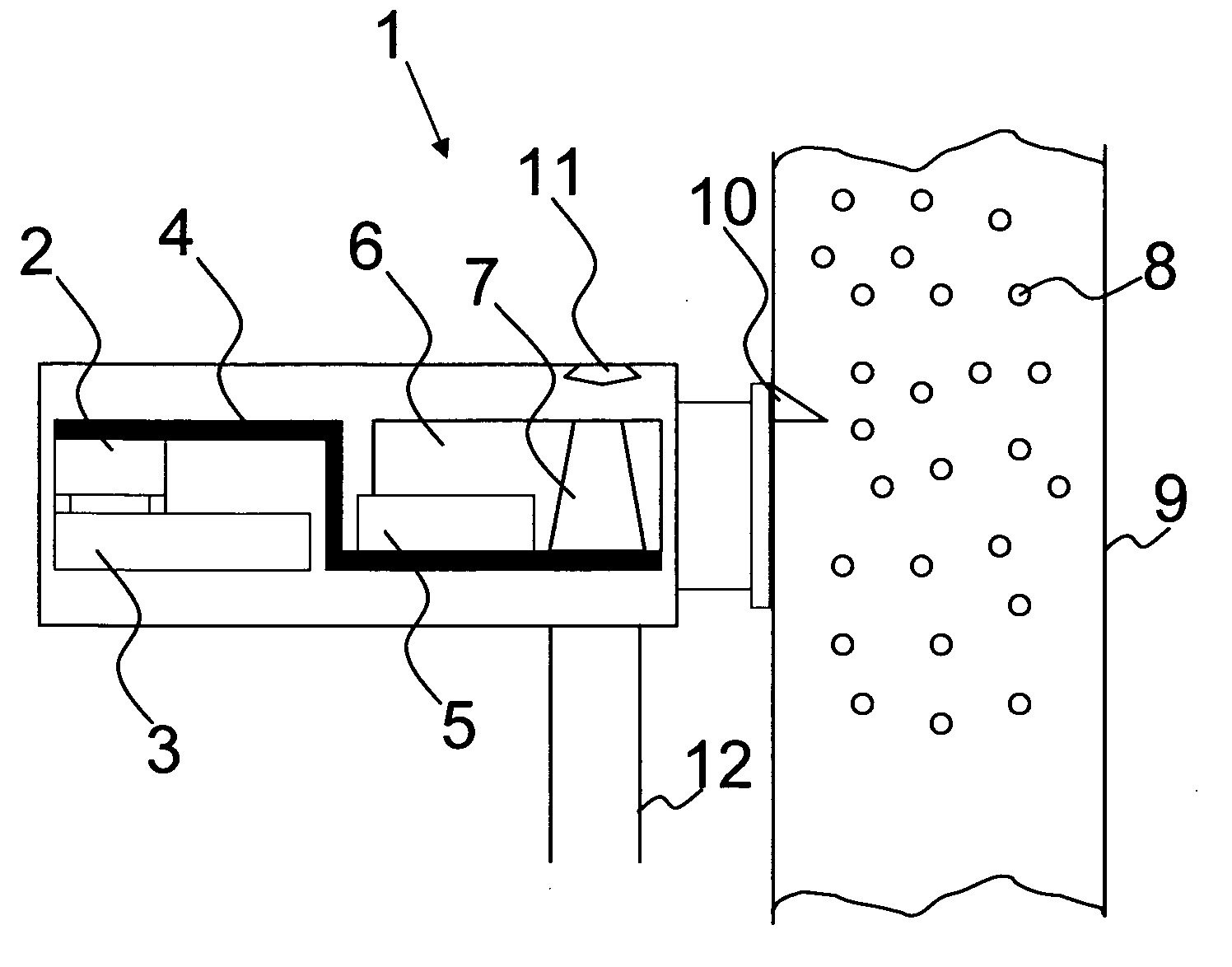
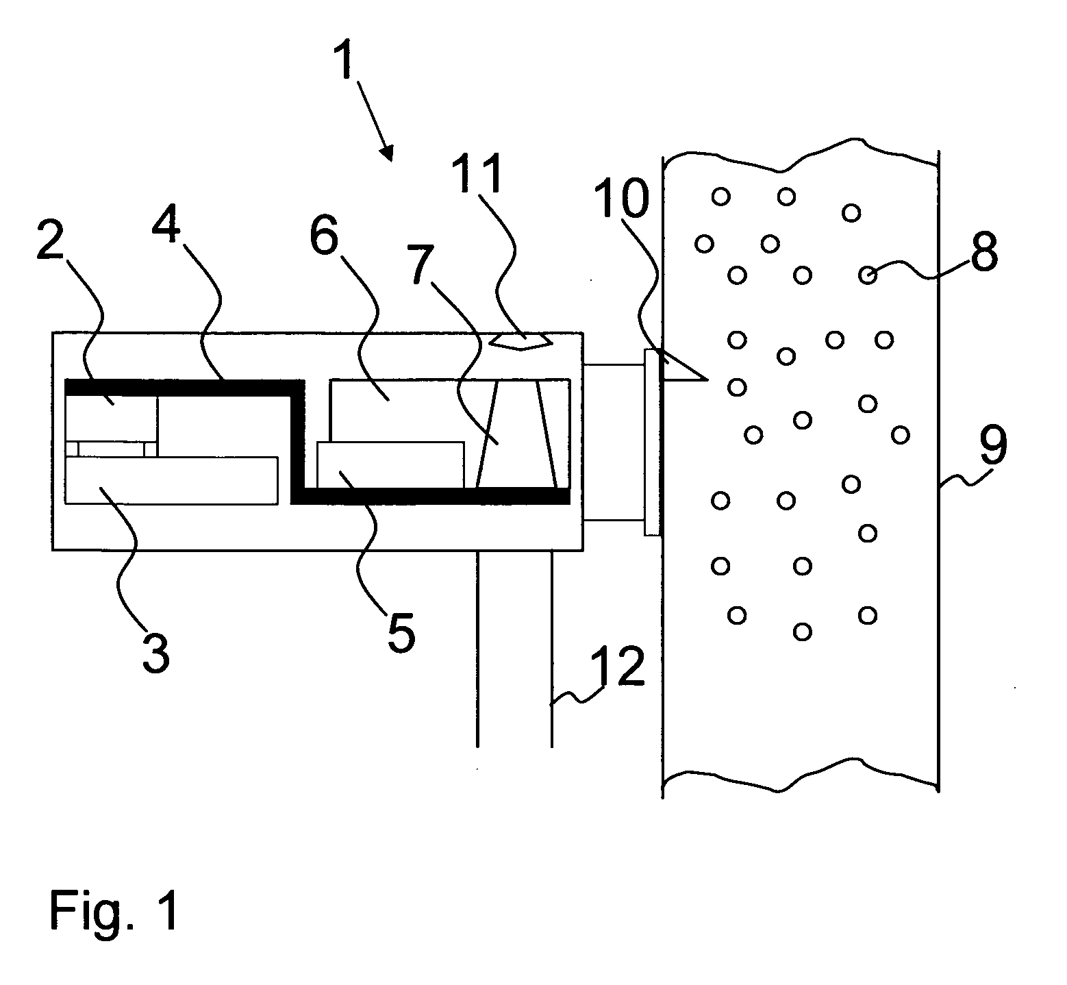
[0039]As previously mentioned, the invention concerns a system which can be mounted at any place in a manufacturing process for diverse products where, e.g., a density determination may be of interest. The density measurement according to the invention is developed with regard to a more optimal design which will facilitate cleaning of the sampling cup and while, at the same time, the scraping off of the product may be substantially reduced in order thereby to improve the weighing result. Furthermore, other measurements may be performed in the sample taken by the sampling cup, whereby a plurality of physical conditions of the product may be determined and used as regulating parameter.

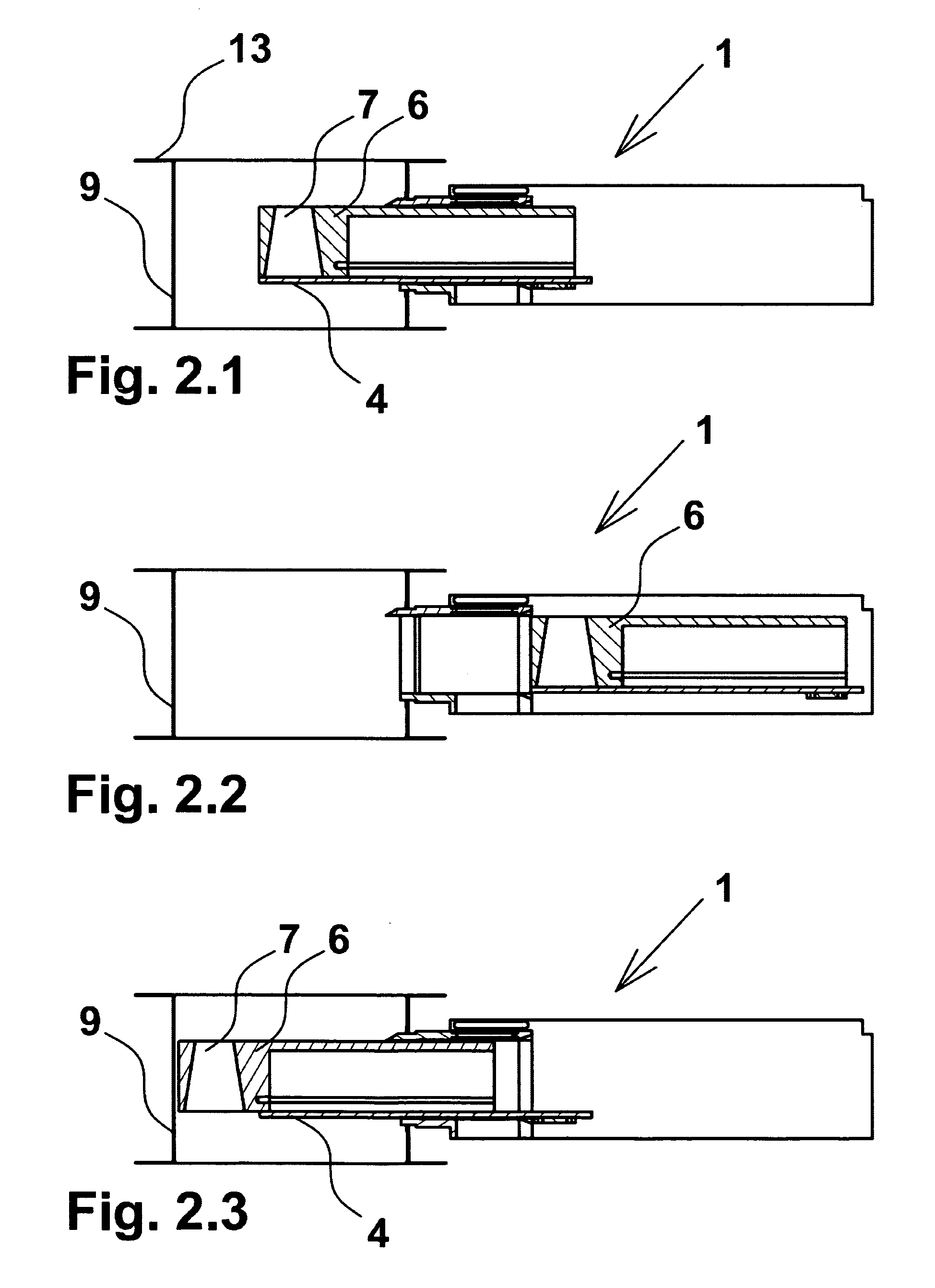
[0040]In FIG. 1 is seen the system 1 which comprises a weighing cell 2 mounted on a first actuator 3 which is displaceable back and forth in horizontal direction. On the weighing cell 2, an arm 4 on which is mounted a further actuator 5. A sampling cup 6 is mounted in connection with the actuator 5 in th...


PUM


Abstract

An apparatus and a method for sampling from a product flow, where the sampling is performed continuously and where the product is collected in a cup for determining physical conditions, for example, weight in relation to volume, and where the cup is emptied after ending the sampling. The apparatus is provided with at least one sampling cup provided with a filling opening and an emptying opening with different cross-sectional areas. It is not necessary to perform a turning movement of the sampling cup in order to empty it. Instead, preferably, the sampling cup is emptied by opening / uncovering the bottom. Emptying of the cup and subsequent cleaning of the cup are effected with open bottom by passage of the product flow through the cup; but, emptying may also occur in a separate duct.

Description

BACKGROUND OF THE INVENTION[0001]1. Field of the Invention[0002]The present invention concerns an apparatus and a method for sampling from a product flow, where the sampling is performed continuously and where the product is collected in a cup, the cup being introduced directly into the product flow for subsequently determining weight in relation to volume or other physical conditions of the product, and wherein the cup is emptied after ending the sampling.[0003]2. Description of Related Art[0004]It is common knowledge to perform sampling, e.g., measuring density of products, such as, e.g., expanded and heat treated products, but also of other products where the products appear with a certain porosity during the manufacturing process, and where the product is desired to be continuously weighed in order thereby to regulate the processes controlling the expansion and thereby the porosity of the weighed product.[0005]Density measurement is presently performed in various ways. Systems t...

Claims


Application Information

Patent Timeline
IPC IPC(8): G01F17/00
CPCG01G15/00G01G17/00G01N9/02G01N1/20G01G21/22
Inventor JORGENSEN, THOMAS KNIEP
Owner SOURCE TECH INC
Why Eureka
Try Eureka