Dimmable LED lamp

a technology of led lamps and led lamps, which is applied in the direction of discharge tubes luminescnet screens, lighting and heating apparatus, light source combinations, etc., can solve the problems of limited light output of current solid state replacement lamps and the inability to match the spherical output of filament-based sources, etc., and achieve high efficiency and high efficiency. , the effect of high efficiency

Inactive Publication Date: 2010-11-18
LIGHT PRESCRIPTIONS INNOVATORS
View PDF4 Cites 33 Cited by
  • Summary
  • Abstract
  • Description
  • Claims
  • Application Information

AI Technical Summary

Benefits of technology

[0005]Embodiments of the present lamps make it possible to overcome the above mentioned thermal limitation by employing the helical vane cooling system described in the above-mentioned U.S. patent application Ser. No. 12 / 687,620. The invention also employs optical features taught in the above-mentioned U.S. patent application Ser. Nos. 12 / 210,096 and 12 / 378,666. These novel optical approaches provide solutions that make it possible to produce a spherical light output similar to that from an incandescent filament in a relatively small package. Embodiments of the present lamps make use of the driver and dimming systems taught in the above-mentioned U.S. patent application Ser. No. 12 / 589,071.
[0006]It is also desirable for the LED lamp to have a very high efficiency. This can be achieved using the approach known as “remote phosphor” taught in the above-mentioned U.S. Pat. Nos. 7,286,296 and 7,380,962. A further principle used in the present lamps to achieve high efficiency is to combine the output from blue LEDs, blue stimulated yellow or green phosphor, and red LEDs. Such a system can achieve high efficiencies without compromising the CRI of the source. This approach to achieving high efficiency was taught in the above-mentioned U.S. Pat. No. 7,144,121. In that patent the outputs from blue LEDs, green phosphor and red LEDs are combined via a dichroic mirror after first being collimated. In embodiments of the present lamps, the output from these three light sources is combined in a spherical phosphor mixing chamber. Embodiments of the present lamps have in common with the devices of U.S. Pat. No. 7,144,121 that the red light is first collimated but differ in that the blue light source is first collimated on its own and then concentrated and sent into a spherical mixing chamber. A portion of the blue light is used to excite the remote phosphor while the remainder escapes through the phosphor. (A small portion of this light is reflected back to the LEDs.) The phosphor layer, which acts as a homogenizer, may reside on the inside of a hollow glass or other transparent or translucent dielectric sphere or alternatively may reside on the outside of a solid or hollow dielectric sphere. In U.S. Pat. No. 7,144,121 the green phosphor is proximate to the blue LED light source, and the combined blue / green light is collimated. Embodiments of the present lamps have an advantage in that the phosphor mixing chamber both homogenizes the three wavelength sources and outputs the desired spherical beam output profile to emulate a filament source.

Problems solved by technology

Also, it would be desirable if the solid state lamp was dimmable (a major problem with the vast majority of the compact fluorescent bulbs that are at present the commonest substitutes for incandescent bulbs.)
Current solid state replacement lamps are typically limited to a flux of around 400 to 480 lumens (equivalent to the flux output of a 40 W incandescent bulb), primarily because of thermal management issues.
Also, the light output from these lamps does not match the spherical output from filament-based sources.

Method used


Image

  • Dimmable LED lamp
  • Dimmable LED lamp
  • Dimmable LED lamp

Examples


Embodiment Construction

[0019]A better understanding of certain features and advantages of the present invention will be obtained by reference to the following detailed description and accompanying drawings, which set forth illustrative embodiments in which various principles of the invention are utilized.

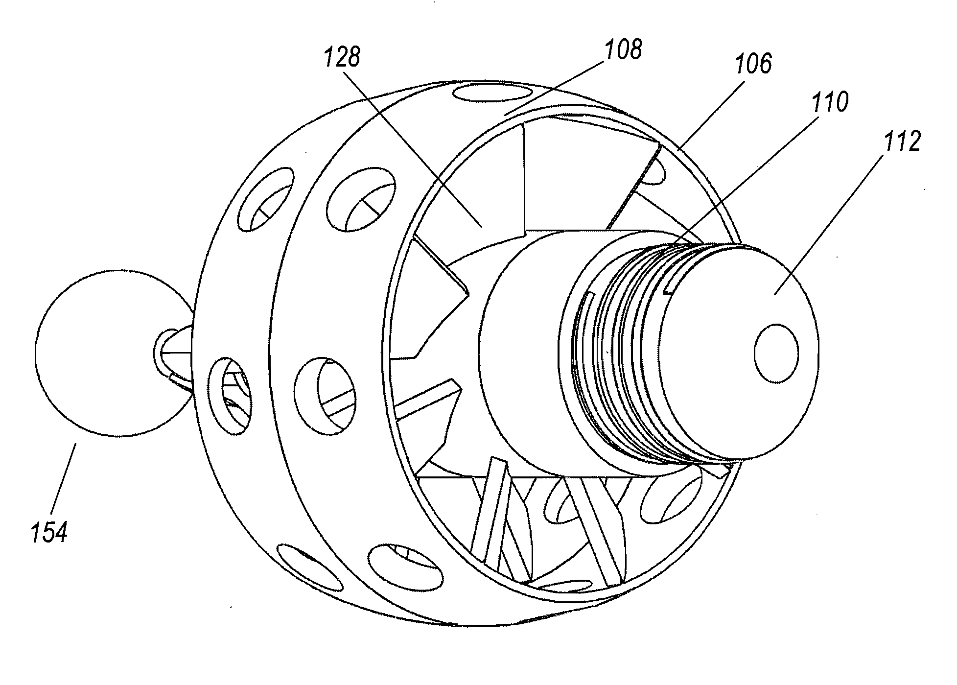
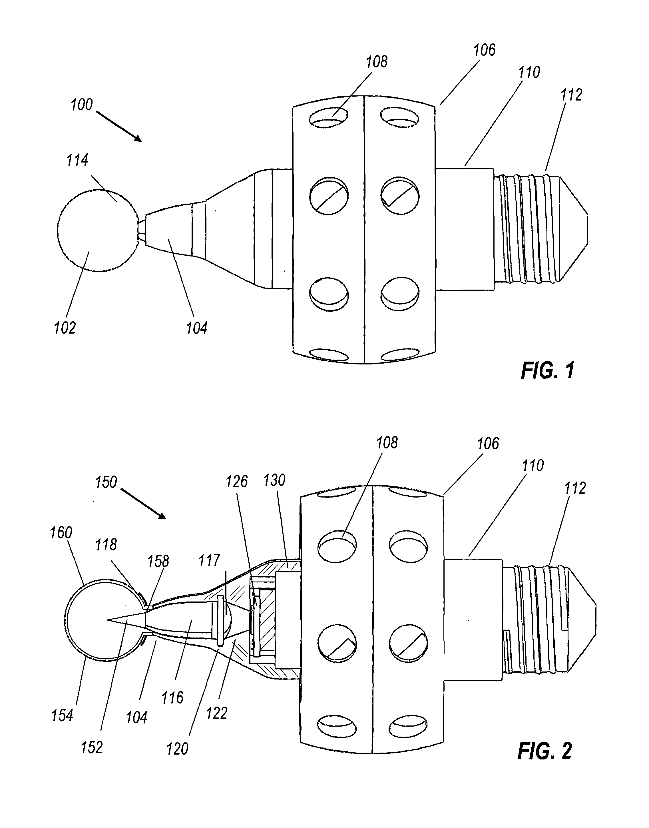
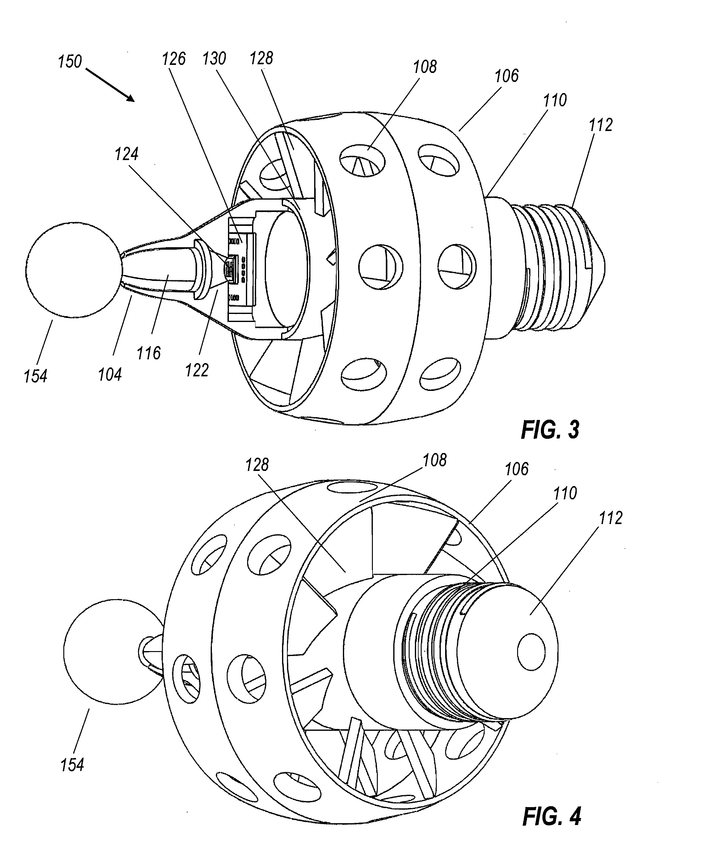
[0020]FIGS. 1 through 4 show embodiments of a dimmable LED lamp, indicated generally by the reference numbers 100 and 150. Referring initially to FIG. 1, lamp 100 comprises a dielectric sphere 102, an external shroud 104, a support ring 106 with holes 108, a body comprising an electronics compartment 110, and a screw-in base 112. The holes 108 enable air currents to flow within support ring 106 no matter at what orientation light bulb 100 is installed. On the outside of dielectric sphere 102 is a thin layer of phosphor 114. The phosphor typically is embedded inside a layer of optical grade epoxy, silicone or other suitable material known to those skilled in this art. Alternatively, the phosphor can be dep...


PUM


Abstract

An LED-powered replacement for the conventional incandescent screw-in light bulb comprises a phosphor coated sphere emitting white light into the same spherical pattern as a frosted incandescent bulb. In one embodiment inside the hollow sphere there is a dielectric cone emitting blue light, which causes the phosphor coating to glow. The blue light comes into the cone from a dielectric totally internally reflecting concentrator (DTIRC), which receives light from a conical reflector surrounding an LED array. The array has blue chips for energizing the phosphor and red chips for supplementing the phosphor light, enabling separate electronic control of the color temperature as well as the overall luminosity of the LED Lamp. Both blue and red chips are controlled by a quantum dimmer.

Description

CROSS REFERENCE TO RELATED APPLICATIONS[0001]This application claims benefit of U.S. Provisional Patent Application No. 61 / 216,182, filed May 13, 2009 by Sun et al. for “Dimmable LED Lamp.”[0002]This application is related to commonly owned co-pending U.S. patent application Ser. No. 12 / 378,666 (publication no. 2009-0225529), filed Feb. 18, 2009 by Falicoff et al. for “Spherically emitting remote phosphor”; co-pending U.S. patent application Ser. No. 12 / 589,071 (publication no. 2010-0097002), filed Oct. 16, 2009 by Shatford et al. for “Quantum Dimming via Sequential Stepped Modulation of LED Arrays”; co-pending U.S. patent application Ser. No. 12 / 687,620, filed Jan. 14, 2010 by Falicoff et al. for “Heat sink with helical fins and Electrostatic Augmentation”; co-pending U.S. patent application Ser. No. 12 / 210,096 (publication no. 2009-0067179) filed Sep. 12, 2008 by Chaves et al. for “Optical Device for LED-Based Lamp”; U.S. Pat. No. 7,144,121 issued Dec. 5, 2006 to Miñano et al. for...

Claims


Application Information

Patent Timeline
Patent Type & Authority Applications(United States)
IPC IPC(8): F21V29/00H01J1/62
CPCF21K9/52F21V3/00F21Y2101/02F21K9/135F21V29/83F21Y2113/005F21V29/677F21V29/74F21V29/78F21K9/56F21K9/232F21K9/61F21K9/64F21Y2113/13F21Y2115/10
Inventor SUN, YUPINFALICOFF, WAQIDISHATFORD, WILL
Owner LIGHT PRESCRIPTIONS INNOVATORS
Why Eureka
Try Eureka