Optical system and optical equipment including the same

a technology of optical equipment and optical system, applied in the field of optical system, can solve the problems of large amount of unnecessary reflected light generated, flare and ghosting, and deterioration of image quality, and achieve the effect of small ghosting occurrence, excellent anti-reflection effect, and easy acquisition

Inactive Publication Date: 2010-11-18
CANON KK
View PDF11 Cites 15 Cited by
  • Summary
  • Abstract
  • Description
  • Claims
  • Application Information

AI Technical Summary

Benefits of technology

[0009]It is an object of the present invention to provide an optical system which has an excellent anti-reflection effect, is small in occurrence of ghost, and easily obtains a high optical performance.
[0017]According to the present invention, the optical system that has the excellent anti-reflection effect, reduces the occurrence of flare and ghost, and has the high optical performance can be obtained.

Problems solved by technology

When reflected light from the lens surface enters an imaging plane to serve as ghost light, the image quality is largely deteriorated.
However, when the radius of curvature of the aspherical surface becomes smaller, an incident angle range of a light beam to the aspherical surface is enlarged, a large amount of unnecessary reflected light is generated from the aspherical surface, and the unnecessary reflected light enters the imaging plane, which causes flare and ghost to frequently occur.
In particular, when the angle of field of the optical system increases, this tendency increases.
When those requirements are inappropriate, the excellent anti-reflection effect is not obtained, the heteromorphous ghost frequently occurs, and the optical system with a high optical performance is difficult to obtain.

Method used


Image

  • Optical system and optical equipment including the same
  • Optical system and optical equipment including the same
  • Optical system and optical equipment including the same

Examples


first embodiment

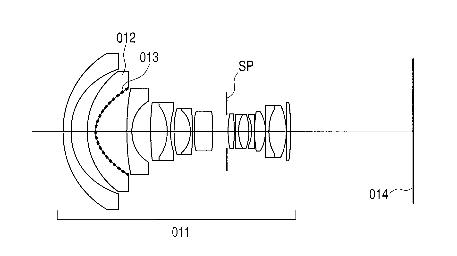
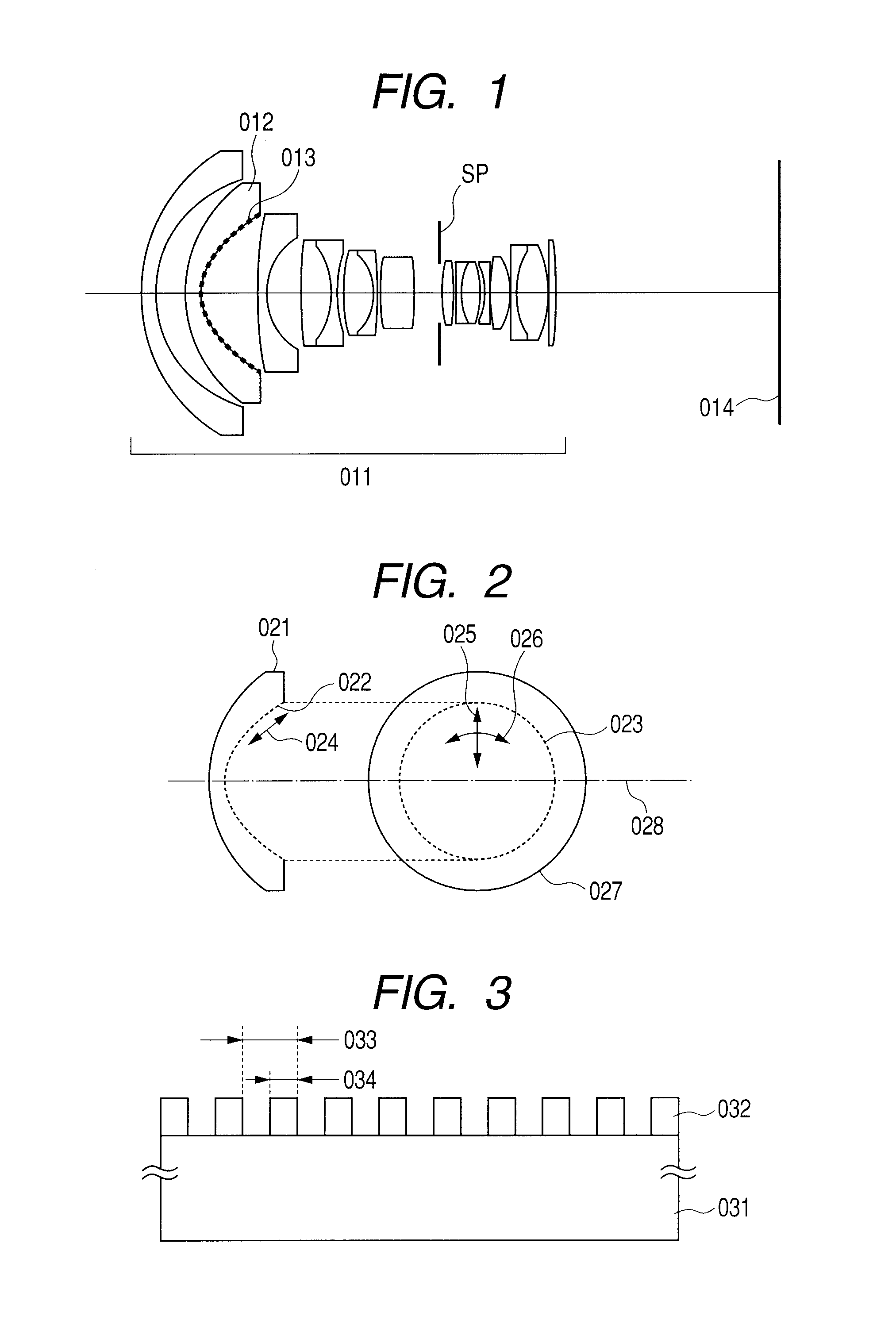
[0031]FIG. 1 is a cross-sectional view of lenses of an optical system according to a first embodiment of the present invention. When the optical system of the first embodiment is used as an image pickup optical system, a left hand in the figure is an object side, and a right hand is an image side. On the other hand, the optical system may be used for a projection optical system such as a projector. In this case, the left hand is a screen, and the right hand is an image to be projected. In this embodiment, an example in which the optical system is used as the image pickup optical system is described below.

[0032]Referring to FIG. 1, an image pickup optical system 011 is of a retrofocus type. An aspherical lens 012 includes a lens surface of an aspherical shape. The aspherical lens 012 includes an aspherical surface 013. An imaging plane is represented by 014. An aperture stop is represented by SP. Table 1 shows a detailed numerical embodiment of the image pickup optical system accordi...

second embodiment

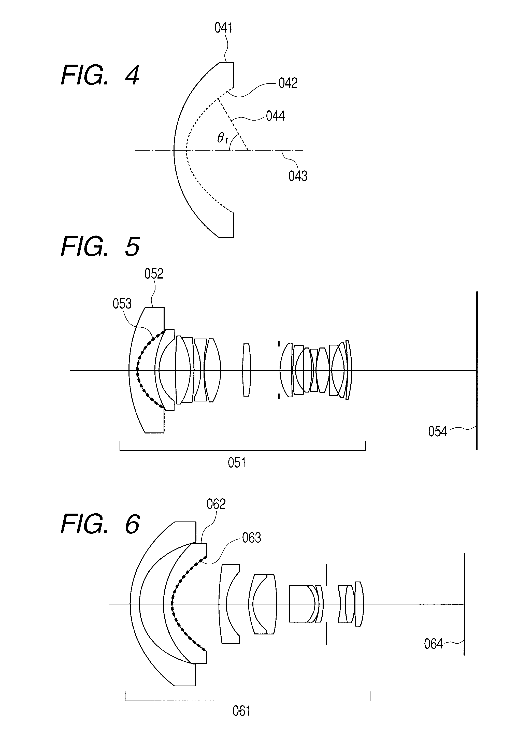
[0056]FIG. 5 is a cross-sectional view of lenses in an optical system according to a second embodiment of the present invention. In the figure, an image pickup optical system is represented by 051, an aspherical lens is represented by 052, an aspherical surface is represented by 053, and an imaging plane is represented by 054. In this embodiment, an image side surface of a first lens from the object side is the aspherical surface 053. The aspherical surface 053 is provided with an anti-reflection structure formed of structural parts made of an inorganic material and finer than the used wavelength. A second numerical embodiment of the second embodiment is shown in Table 2 like the first numerical embodiment.

[0057]In this embodiment, the aspherical surface 053 is 7.9×10⁻⁴ in the value on the left-hand side of Expression (2), which satisfies the condition of Expression (2). For that reason, ghost occurring on the aspherical surface 053 is liable to be a heteromorphous image. Under the ...

third embodiment

[0059]FIG. 6 is a cross-sectional view of lenses in an optical system according to a third embodiment of the present invention. In the figure, an image pickup optical system is represented by 061, an aspherical lens is represented by 062, an aspherical surface is represented by 063, and an imaging plane is represented by 064. In this embodiment, an image side surface of a second lens from the object side is the aspherical surface 063. The aspherical surface 063 is provided with an anti-reflection structure formed of structural parts made of an inorganic material and finer than the used wavelength. A third numerical embodiment of the third embodiment is shown in Table 3 like the first numerical embodiment. The aspherical surface 063 is 8.4×10⁻¹ in the value on the left-hand side of Expression (2), which satisfies the condition of Expression (2). For that reason, ghost occurring on the aspherical surface 063 is liable to be a heteromorphous image. Under the circumstance, when the anti...


PUM

PropertyMeasurementUnit
half aperture angleaaaaaaaaaa
anti-reflection structureaaaaaaaaaa
radius of curvatureaaaaaaaaaa

Abstract

Provided is an optical system with an excellent anti-reflection effect and ghost suppression effect including an aspherical lens having at least one of an incident surface and an exiting surface of an optical glass formed of an aspherical surface, in which: the aspherical surface includes an anti-reflection structure formed thereon, the anti-reflection structure having an anti-reflection function and including multiple inorganic structural parts finer than a used wavelength; and the aspherical surface has a point that satisfies the following expression: |(1 / Rm−1 / Rs) / Rm|>5.0×10⁻⁵, where Rm denotes a radius of curvature in a meridional direction at an arbitrary point, and Rs denotes a radius of curvature in a sagittal direction at the arbitrary point.

Description

BACKGROUND OF THE INVENTION[0001]1. Field of the Invention[0002]The present invention relates to an optical system which effectively performs anti-reflection on a lens surface while keeping a high optical performance, and is suitable for an optical equipment such as a video camera or a projector.[0003]2. Description of the Related Art[0004]There is a demand that an optical system used for an optical equipment such as a camera or a projector provide a high optical performance so as to meet the high performance of the optical equipment. In order to obtain the optical system with the higher optical performance, it is effective to use an aspherical lens in addition to a spherical lens. When reflected light from the lens surface enters an imaging plane to serve as ghost light, the image quality is largely deteriorated. Therefore, in order to obtain the optical system with the high optical performance, it is effective to provide an anti-reflection structure for preventing reflection on th...

Claims


Application Information

Patent Timeline
Patent Type & Authority Applications(United States)
IPC IPC(8): G02B3/02G02B1/118G02B1/11G02B13/00G02B13/18
CPCG02B1/118G02B13/06G02B3/02G02B27/0018G02B1/11G02B13/18
Inventor SANO, DAISUKEMOMOKI, KAZUHIKOOKUNO, TAKEHARU
Owner CANON KK
Why Eureka
Try Eureka