Focus detection apparatus

a detection apparatus and focus technology, applied in the direction of mountings, instruments, exposure control, etc., can solve the problems of reducing affecting the detection accuracy of displacement between two images, and the lens aberration becomes relatively large, so as to achieve high focus detection accuracy

Inactive Publication Date: 2010-11-18
CANON KK
View PDF5 Cites 11 Cited by
  • Summary
  • Abstract
  • Description
  • Claims
  • Application Information

AI Technical Summary

Benefits of technology

[0024]As described above, according to the present invention, since a type of a light source irradiating an object can be determined using an output signal from a photometry sensor and an image signal output by a focus detection sensor can be compensated based on the determination result, focus detection accuracy can be improved even during photography performed under object-irradiating light sources of different types.
[0025]In addition, with a compensation operation method according to the present invention, since the operation method only requires compensation coefficients corresponding to two types of light sources, the capacity of a memory for storing data required to perform operations can be reduced.
[0026]Furthermore, with another compensation operation method according to the present invention, since the operation method only requires a compensation coefficient corresponding to one light source type, the capacity of the memory for storing data required to perform operations can be further reduced.

Problems solved by technology

However, since a simple lens structure is required in consideration of a permissible size, cost, and convenience of production of the focus detection apparatus, lens aberration becomes relatively large.
However, with the focus detection apparatus disclosed in Japanese Patent Application Laid-Open No. 560-101514 described above, depending on the type of light source illuminating an object, there may be cases where shading between sensors cannot be compensated.
As shown, depending on the type of light source irradiating an object, an uncompensated region of shading remains between sensors, causing a reduction in the detection accuracy of a displacement between two images.

Method used


Image

  • Focus detection apparatus
  • Focus detection apparatus
  • Focus detection apparatus

Examples


first embodiment

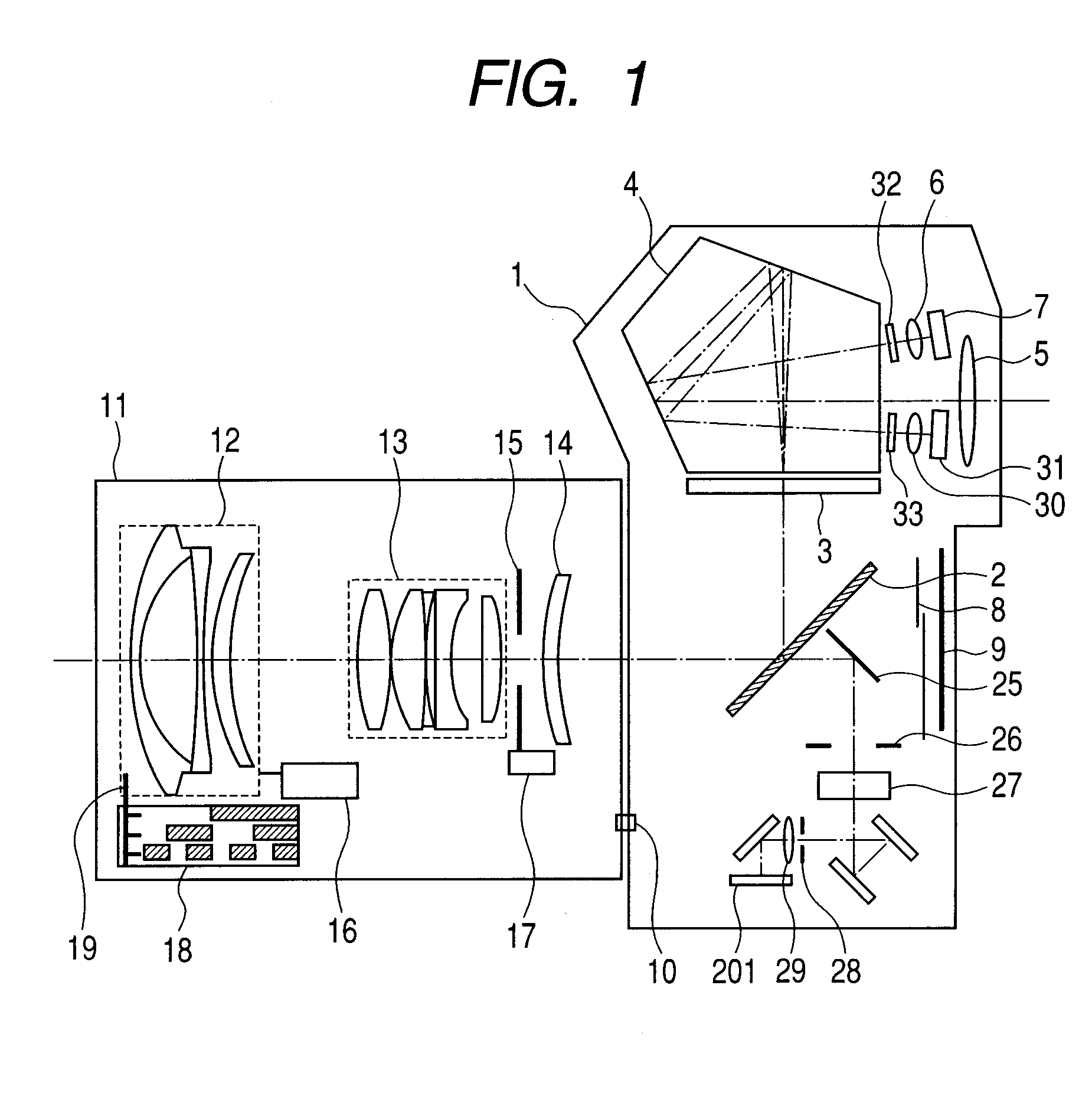
[0051]FIG. 1 is a configuration diagram illustrating an auto-focus camera system according to an exemplary embodiment of the present invention and which includes a single lens reflex camera and an interchangeable lens to be mounted on the camera. The diagram primarily illustrates an optical positional relationship of the system.

[0052]In the diagram, a photographing lens 11 is mounted on a front face of a camera main body 1. Optical parts, mechanical parts, an electric circuit, and a film or an imaging element such as a CCD are housed in the camera main body 1 so as to enable photography of a picture or an image. An optical member 2 that is a main mirror (hereinafter referred to as an optical member) is obliquely provided in a photographing optical path in a finder observation state and is withdrawn from the photographing optical path in a photographing state. In addition, the optical member 2 is arranged as a semi-transparent mirror that partially transmits or reflects an incident l...

second embodiment

[0095]In the first embodiment, compensation is performed by selecting, according to a light source determination result, any one of a plurality of shading coefficients stored in advance.

[0096]The second embodiment described below is an exemplary embodiment that performs a compensation operation that differs from the first embodiment.

[0097]FIG. 11 is a flow chart for describing an auto-focusing operation of a camera related to the second embodiment of the present invention. A control flow illustrated in FIG. 11 will be described with reference to FIG. 14 described earlier.

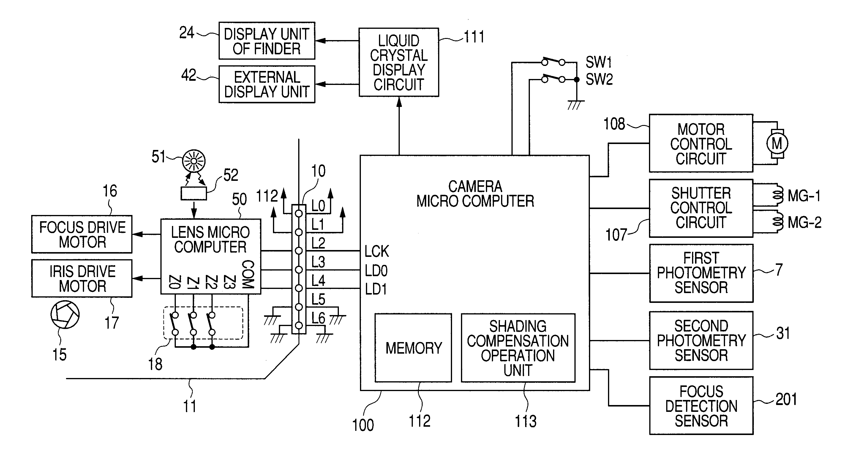
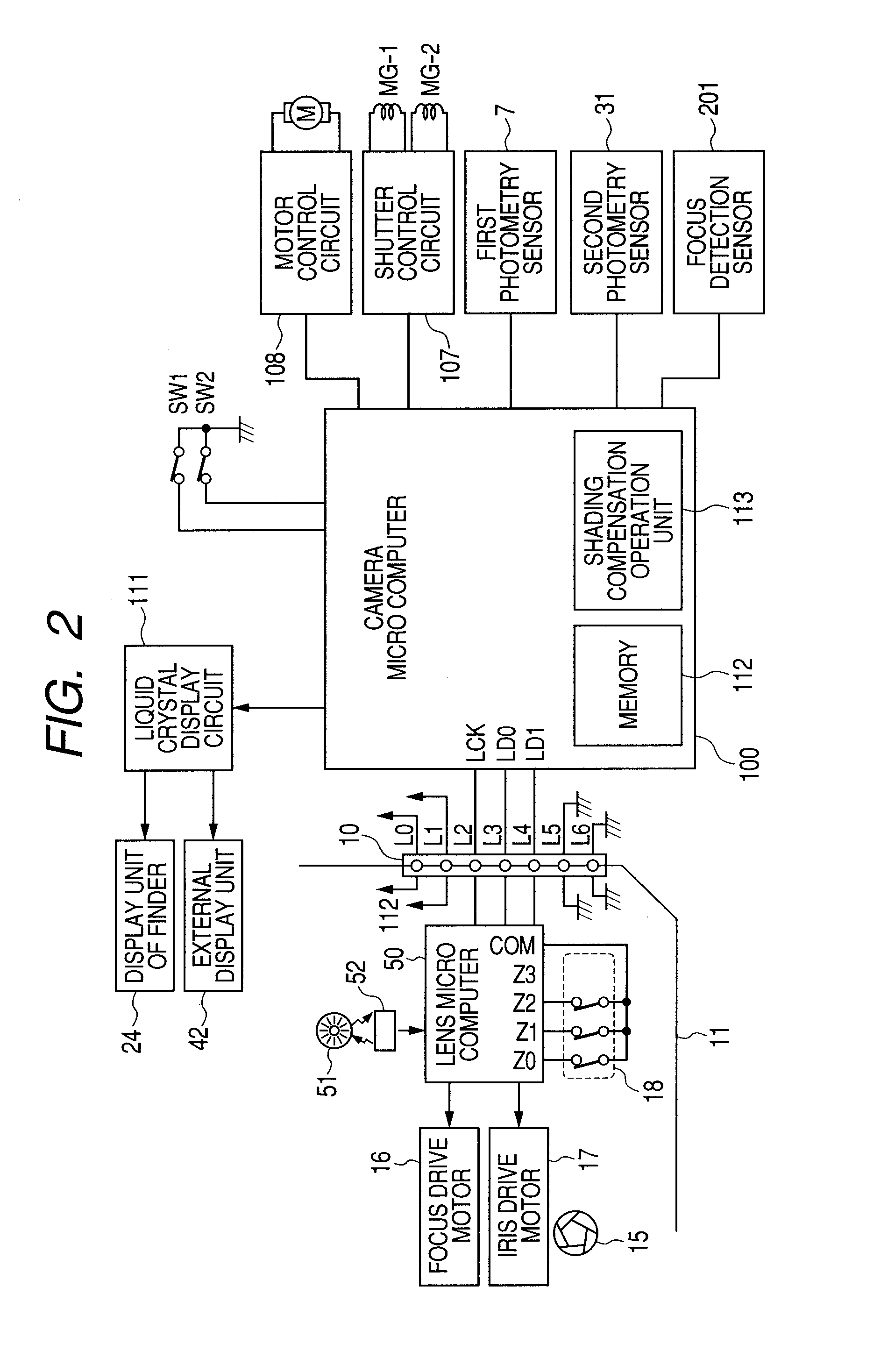
[0098]Operation starts at step S401 when the switch SW1 on the camera main body 1 illustrated in FIG. 2 is pressed. In this case, the camera microcomputer 100 performs an accumulation operation of the line sensors 211a, 211b, 212a, and 212b in the focus detection sensor 201. After accumulation is started, an accumulation status is monitored according to a signal from the focus detection sensor 201. Accumulation is s...

third embodiment

[0109]Cameras according to the first embodiment and the second embodiment perform compensation based on light source detection results and a plurality of shading coefficients stored in advance.

[0110]The third embodiment described below is an exemplary embodiment that performs a compensation operation that differs from the first embodiment and the second embodiment.

[0111]FIG. 12 is a flow chart for describing an auto-focusing operation of a camera related to the third embodiment of the present invention. A control flow illustrated in FIG. 12 will be described with reference to FIG. 14 described earlier.

[0112]Operation starts at step S501 when the switch SW1 on the camera main body 1 illustrated in FIG. 2 is pressed. In this case, the camera microcomputer 100 performs an accumulation operation of the line sensors 211a, 211b, 212a, and 212b in the focus detection sensor 201. After accumulation is started, an accumulation status is monitored according to a signal from the focus detectio...


PUM


Abstract

A focus detection apparatus that measures, in advance, and stores shading coefficients for light sources of different types, and in a focus detection operation, generates light source information for determining a light source that irradiates an object based on outputs from a plurality of photometry sensors with different spectral characteristics and switches the shading coefficient of a focus detection sensor among shading coefficients stored according to the light source information.

Description

BACKGROUND OF THE INVENTION[0001]1. Field of the Invention[0002]The present invention relates to the improvement of focus detection accuracy under light sources of different types in an auto-focus camera.[0003]2. Description of the Related Art[0004]Film / digital single lens reflex cameras commonly use a so-called TTL (Through The Lens) phase difference detection-type focus detection (hereinafter also referred to as AF) method in which a light flux passed through a photographing lens is split by a beam splitter, images of the respective light fluxes are formed on a focus detection sensor by two imaging lens with displaced optical axes, a defocus amount is calculated from a displacement between the two formed images, and focusing is achieved by driving the photographing lens according to the calculated defocus amount.[0005]FIG. 14 illustrates an example of a phase difference detection-type focus detection apparatus that uses a secondary imaging system. In the apparatus, a field lens 10...

Claims


Application Information

Patent Timeline
Patent Type & Authority Applications(United States)
IPC IPC(8): G03B13/00
CPCG03B13/00G02B7/285
Inventor ICHIMIYA, TAKASHI
Owner CANON KK
Why Eureka
Try Eureka