
Metallic Layer-by-Layer Photonic Crystals for Linearly-Polarized Thermal Emission and Thermophotovoltaic Device Including Same

a photonic crystal and metal layer technology, applied in the direction of instruments, optical radiation measurement, therapy, etc., can solve the problems of major efficiency loss, inefficient conversion of total energy carried by photons from the sun to electricity,

Active Publication Date: 2010-11-25
IOWA STATE UNIV RES FOUND
View PDF34 Cites 13 Cited by
  • Summary
  • Abstract
  • Description
  • Claims
  • Application Information

AI Technical Summary

Benefits of technology

[0010]In view of the above, embodiments of the present invention provide new and improved polarized thermal emitters (PTEs) that overcome one or more of the problems existing in the art. More particularly, embodiments of the present invention provide new and improved PTEs that are particularly well suited for application in thermophotovoltaic (TPV) and other applications. Embodiments of the present invention provide consistently polarized thermal emission with spectrally engineered emissivity. In embodiments of the present invention, highly polarized thermal emission available at normal emergence, high thermal radiation power, tunable emission range is provided.

Problems solved by technology

As such, the total energy carried by photons from the sun is not efficiently converted to electricity.
The reflection of incoming photons at the surface of the photodiode is significant because of the high refractive index of most semiconductor materials and can result in major efficiency loss unless a high-cost antireflection layer is applied.

Method used


Image

  • Metallic Layer-by-Layer Photonic Crystals for Linearly-Polarized Thermal Emission and Thermophotovoltaic Device Including Same
  • Metallic Layer-by-Layer Photonic Crystals for Linearly-Polarized Thermal Emission and Thermophotovoltaic Device Including Same
  • Metallic Layer-by-Layer Photonic Crystals for Linearly-Polarized Thermal Emission and Thermophotovoltaic Device Including Same

Examples


Embodiment Construction

[0032]Before turning specifically to the drawings, it is noted that thermal radiation (TR) properties of materials have been rigorously studied because of the importance of TR in various scientific and practical applications. Recently, periodic microstructures including photonic crystals have been shown to enable tuning of the spectral distribution of TR. Furthermore, polarization properties of TR can be tuned by planar gratings, photonic crystals and elongated nano-heaters. These controls of spectral and polarization properties of TR are potentially very important especially for thermophotovoltaic (TPV) devices.

[0033]Indeed, and as will be discussed in greater detail below, tailoring the TR properties of the emitter in a TPV device to match the conversion characteristics of the photovoltaic cell has the potential to greatly increase energy conversion efficiency. Moreover, the polarized TR source can also be extended to biological and chemical applications as many chemical substance...


PUM

PropertyMeasurementUnit
wavelengthsaaaaaaaaaa
acceptance angleaaaaaaaaaa
polarization angleaaaaaaaaaa

Abstract

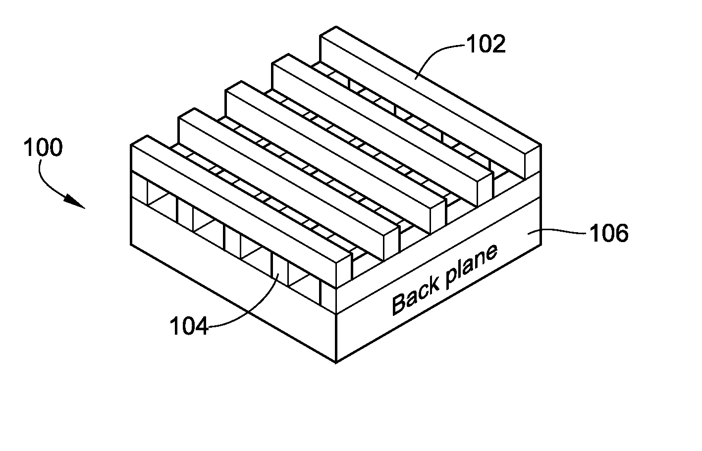
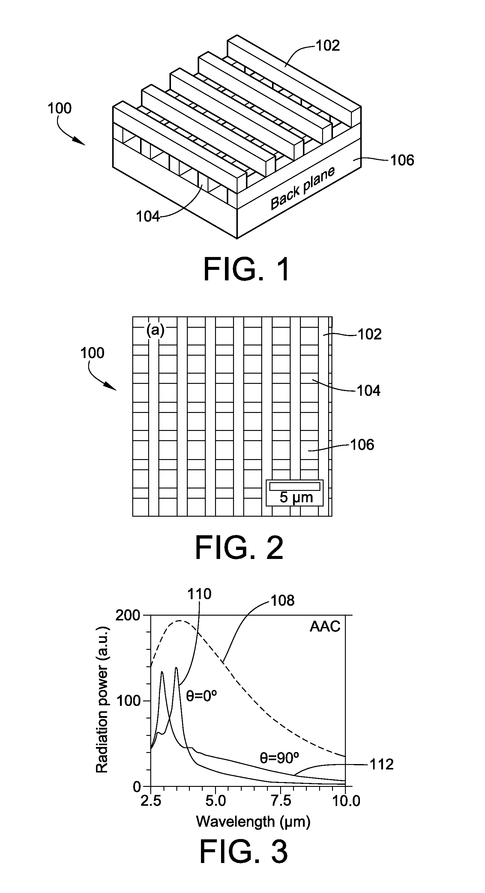
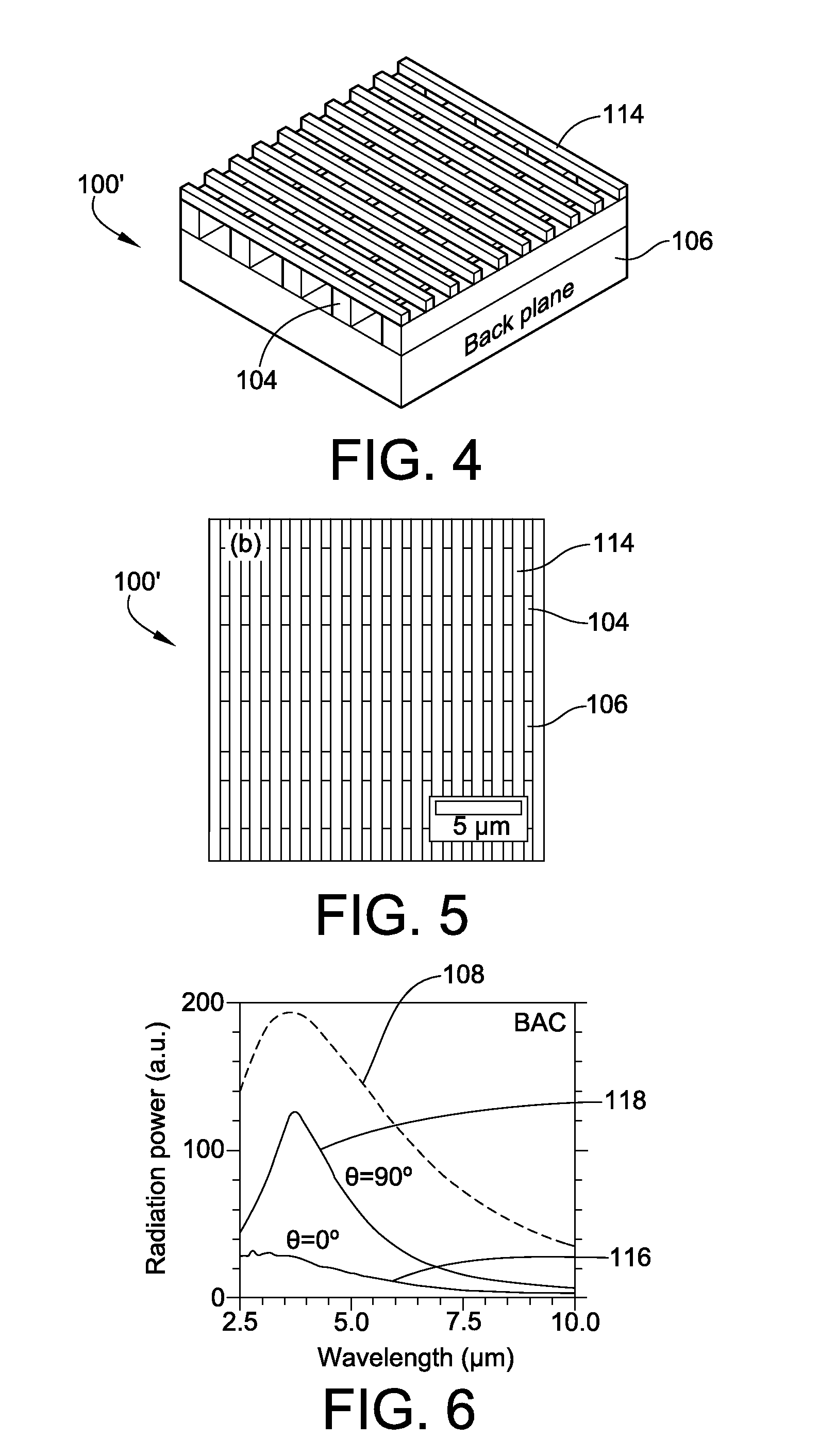
Metallic thermal emitters consisting of two layers of differently structured nickel gratings on a homogeneous nickel layer are fabricated by soft lithography and studied for polarized thermal radiation. A thermal emitter in combination with a sub-wavelength grating shows a high extinction ratio, with a maximum value close to 5, in a wide mid-infrared range from 3.2 to 7.8 μm, as well as high emissivity up to 0.65 at a wavelength of 3.7 μm. All measurements show good agreement with theoretical predictions. Numerical simulations reveal that a high electric field exists within the localized air space surrounded by the gratings and the intensified electric-field is only observed for the polarizations perpendicular to the top sub-wavelength grating. This result suggests how the emissivity of a metal can be selectively enhanced at a certain range of wavelengths for a given polarization.

Description

CROSS-REFERENCE TO RELATED PATENT APPLICATION[0001]This patent application claims the benefit of U.S. Provisional Patent Application No. 61 / 179,468, filed May 19, 2009, the entire teachings and disclosure of which are incorporated herein by reference thereto.STATEMENT REGARDING FEDERALLY SPONSORED RESEARCH AND DEVELOPMENT[0002]This invention was made in part with Government support under Grant Number DE-ACO2-06CH11358 awarded by the Department of Energy. The Government has certain rights in this invention.FIELD OF THE INVENTION[0003]This invention generally relates to thermophotovoltaic (TPV) devices, and more particularly to polarized thermal emitters (PTE) for use in TPV devices.BACKGROUND OF THE INVENTION[0004]As the sun is one of the most sustainable and reliable future sources of energy, photovoltaic (PV) devices are highlighted in both research and industrial areas. A photodiode in the PV devices creates a pair of charge carriers when an incident photon has an energy larger th...

Claims


Application Information

Patent Timeline
Patent Type & Authority Applications(United States)
IPC IPC(8): H01L35/02G01J3/10
CPCG01J3/108H02S10/30G01J5/522Y02E10/50G01J5/53
Inventor LEE, JAE-HWANGHO, KAI-MINGCONSTANT, KRISTEN P.
Owner IOWA STATE UNIV RES FOUND
Learn More