
Charged particle detection system and method

a particle detection and charge technology, applied in the field of charged particle detection system, can solve the problems of occupying space in the vacuum system, multiple detectors increasing system cost, etc., and achieve the effect of improving selectivity and detection efficiency

Active Publication Date: 2010-11-25
EL MUL TECH
View PDF39 Cites 39 Cited by
  • Summary
  • Abstract
  • Description
  • Claims
  • Application Information

AI Technical Summary

Benefits of technology

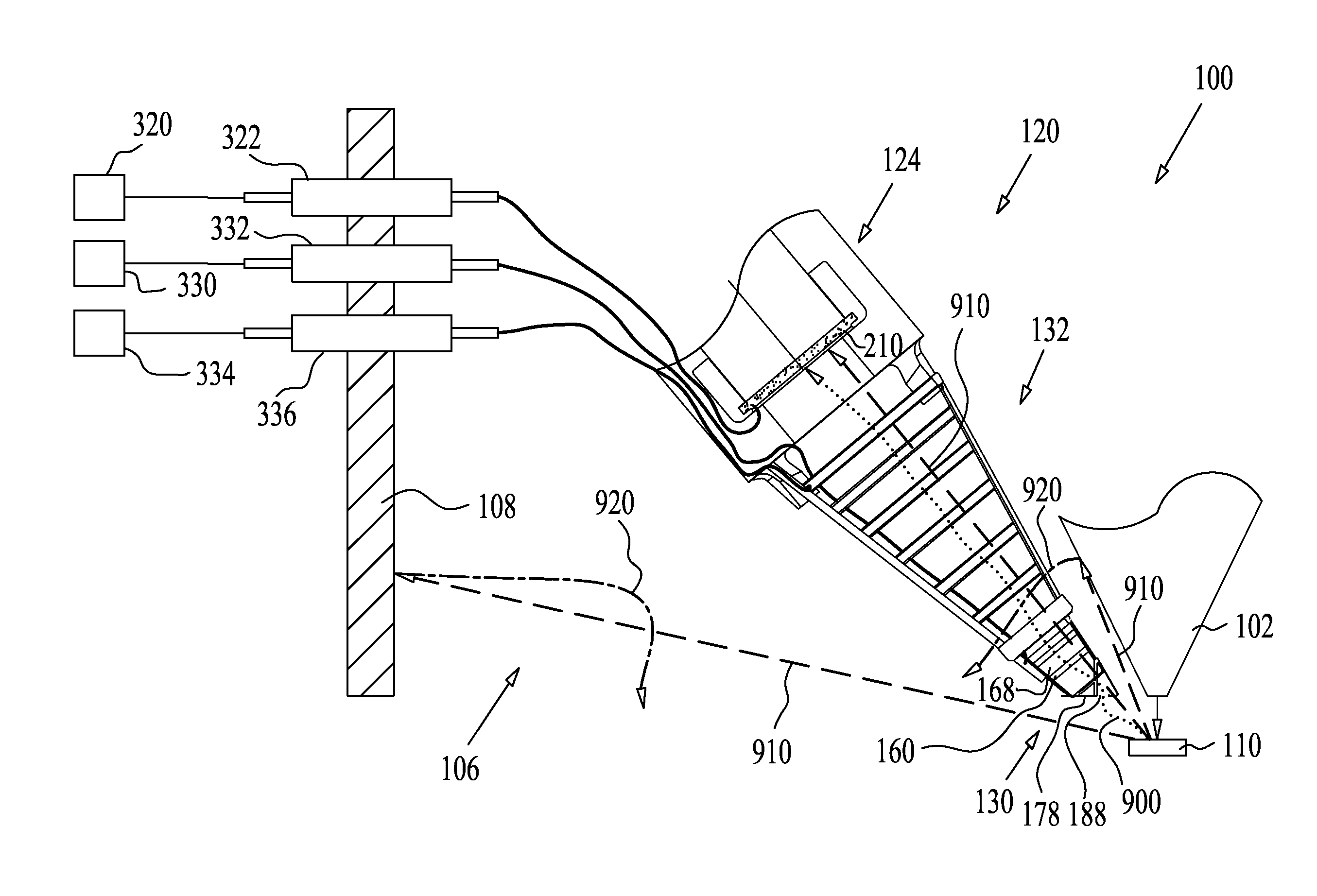
[0007]There is a need in the art and it would be advantageous to have a detection system with improved selectivity and detection efficiency for: secondary electrons and / or secondary ions emitted from the specimen, backscattered electrons and / or backscattered ions emitted from the specimen; and / or tertiary electrons and / or tertiary ions, which are emitted from a surface (defined as any surface other than the specimen) due to impingement of a backscattered electron, or a backscattered ion, or a neutral atom or any particle thereon.
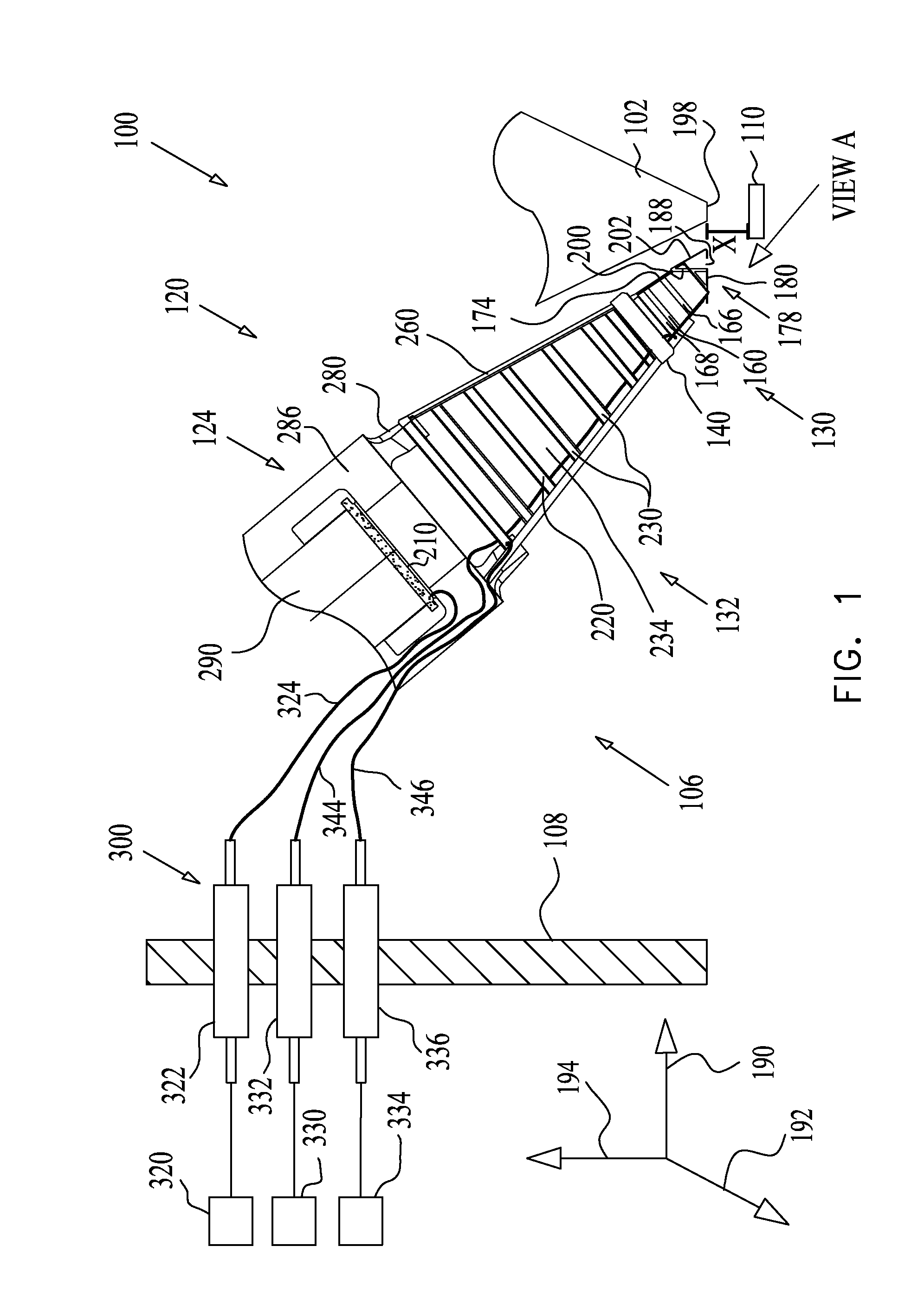
[0020]According to another general aspect, the present invention provides a method for selectively detecting charged particles produced due to operation of a charged particle beam column irradiating a specimen. The method is carried out by the system described above, and comprises selectively electrically biasing the proximal grid and the distal grid of the charged particle detection system so as to urge or compel the selected type of particle to be accelerated to the charged particle detector, and to repel the unselected type of particle so as to prevent the unselected particle from being accelerated to the charged particle detector.

Problems solved by technology

Multiple detectors increase system cost and occupy space in the vacuum system, which may be needed for specimen manipulations.

Method used


Image

  • Charged particle detection system and method
  • Charged particle detection system and method
  • Charged particle detection system and method

Examples


Embodiment Construction

[0037]As indicated above, the present invention is intended to be used with charged particle detection systems and the embodiments will therefore be described below with reference to this application. The principles of the charged particle detection systems according to the present invention may be better understood with reference to the drawings and the accompanying description, wherein similar reference numerals have been used throughout to designate identical elements. It should be understood that these drawings, which are not necessarily to scale, are given for illustrative purposes only and are not intended to limit the scope of the invention. Examples of constructions, materials, dimensions, and fabrication processes are provided for selected elements. Those versed in the art should appreciate that many of the examples provided have suitable alternatives which may be utilized.

[0038]For purposes of explanation, specific configurations and details are set forth in order to provi...


PUM

PropertyMeasurementUnit
voltageaaaaaaaaaa
energy levelsaaaaaaaaaa
energy levelaaaaaaaaaa

Abstract

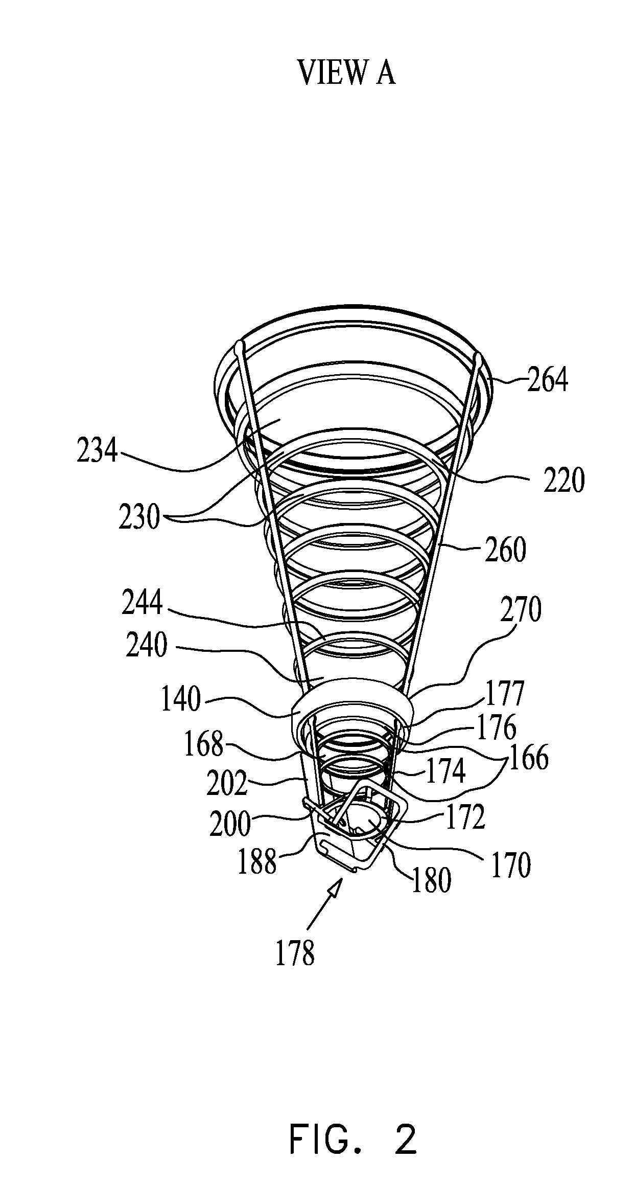
A system for selectively detecting charged particles produced due to operation of a charged particle beam column irradiating a specimen, including a proximal grid being selectively electrically biasable and configured for controllably directing the charged particles by electrically focusing the charged particles to compel selected secondary charged particles, whereupon being selected from the charged particles, to be attracted thereto, and to repel unselected secondary charged particles therefrom, a distal grid spaced apart from the proximal grid and separated therefrom by a gap and being selectively electrically biasable and configured for attracting the selected secondary and / or tertiary charged particles, whereupon being selected from the charged particles, to the distal grid, and to repel unselected tertiary charged particles therefrom, and a charged particle detector configured for detecting selected secondary charged particles attracted to the proximal and / or distal grid and detecting selected tertiary charged particles attracted to the distal grid, that impinge thereupon.

Description

CROSS-REFERENCE TO CO-PENDING APPLICATIONS[0001]Applicant hereby claims priority benefit of U.S. Provisional Patent Application Ser. No. 61 / 180,876, filed on May 24, 2009, and titled “An Electron Detector Assembly,” which is incorporated herein by reference in its entirety.FIELD OF THE INVENTION[0002]The present invention generally relates to a charged particle detection system, and in particular, to a charged particle detector assembly capable of detecting particles of different types, such as, positive and negative ions, secondary ions (SI) and secondary electrons (SE), backscattered ions (BSI) and backscattered electrons (BSE), tertiary ions (SI3) and tertiary electrons (SE3), sputtered ions, etc.BACKGROUND OF THE INVENTION[0003]Charged particle beam systems employed for inspection and / or imaging purposes typically generate a primary beam, of electrons or ions, which is focused onto the surface of a specimen by a charged particle beam column. The detection process generally invol...

Claims


Application Information

Patent Timeline
Patent Type & Authority Applications(United States)
IPC IPC(8): G01N23/00
CPCH01J37/244H01J2237/24485H01J37/28
Inventor ZARCHIN, ORENSHOFMAN, SEMYON
Owner EL MUL TECH
Learn More