
Measuring and Correcting Errors in a Transmit Chain with an IQ Up-Converter and IQ Down-Converter

a transmit chain and iq technology, applied in the field of linearization of systems, can solve the problems of high sampling rate, risk of spurious frequency generation, and need an extra synthesizer, and achieve the effects of reducing spurious interference, high speed, and reducing cos

Active Publication Date: 2010-11-25
APPLE INC
View PDF13 Cites 45 Cited by
  • Summary
  • Abstract
  • Description
  • Claims
  • Application Information

AI Technical Summary

Benefits of technology

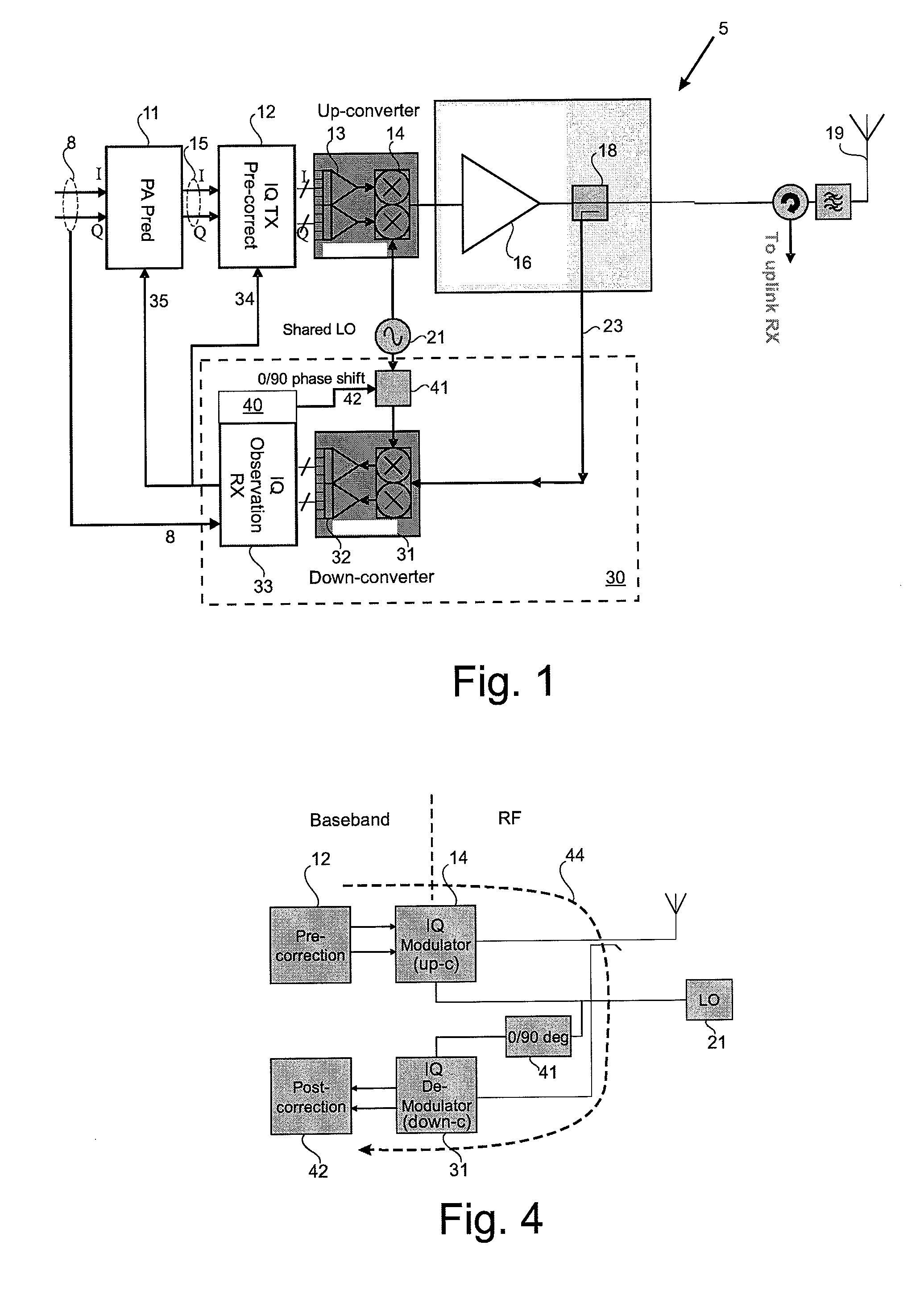
[0012]Because signal impairments introduced by the transmit path and the observation receiver can be separately identified, and corrected for, it is possible to use an IQ architecture in the observation receiver and thereby avoid the need for very high speed, wide bandwidth components of an IF observation receiver. Since both transmit path and observation path now use the same LO frequency, one less frequency synthesizer is required, which reduces cost and also helps to reduce spurious interference between the different LO frequencies.
[0013]The phase shift can be selectively switched between two convenient phase values, such as 0 and 90 degrees. Analysis of the observed signal for both phase states allow the quadrature errors introduced by each of the down-converter and up-converter to be separately identified and corrected for. The different phase states could be applied to the LO signal applied to the up-converter or the down-converter, but it is preferable to apply the phase shift only to the down-converter, since this avoids introducing further impairments to the transmitted signal. Advantageously, the phase shift between the two states of the local oscillator signal applied to the down-converter is set at a value of 90°, as this simplifies the process of determining when impairments have been minimized and helps to simplify the computation of correction parameters. However, the invention is not limited to a phase shift of 90°, and any other suitable value can be used.

Problems solved by technology

A disadvantage of this arrangement is that the ADC must operate at a very high sampling rate.
Also, where the up-converter directly up-converts to RF, the LO required for the up-converter operates at a different frequency to the LO in the down-converter of the observation receiver and therefore requires an extra synthesizer and risks danger of spurious frequency generation.
However, an IQ down-converter (or up-converter) architecture can add their own impairments to the transmitted signal or observation signal.
These impairments are due to differences in the I and Q paths, and can arise in a mixer, anti-alias filter or ADC parts of the down-converter.
This has inhibited the use, and effectiveness, of an IQ ADC architecture in the observation receiver path.
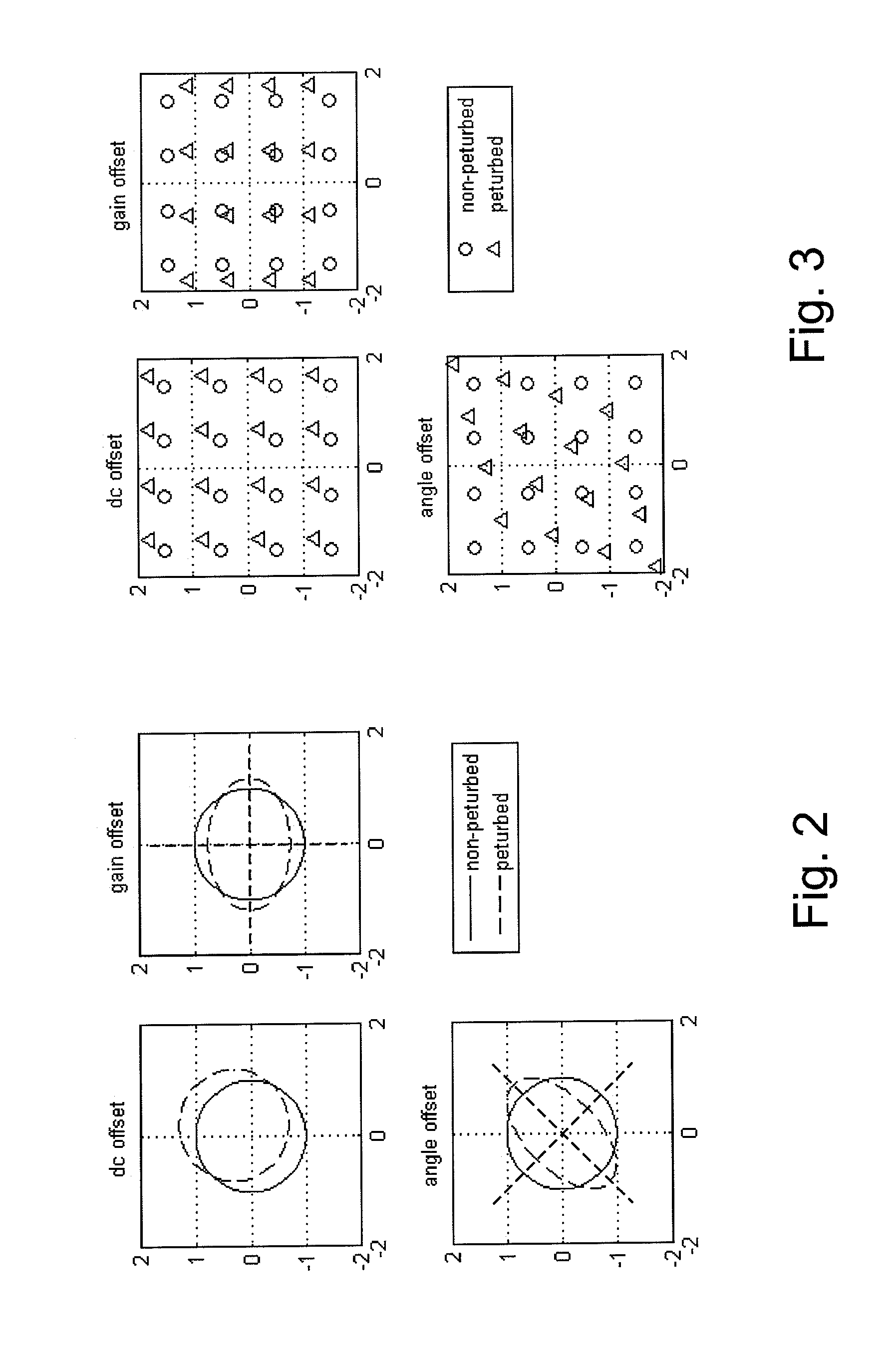
An IQ up-converter will typically add dc, gain offset and angle offset impairments resulting in LO leakage and quadrature images in the RF spectrum.
Even once the IQ errors in the up-converter are compensated for, the errors in the down-converter impair the observation signal used to control the RF amplifier predistortion and limit the effectiveness of the amplifier predistortion correction loop.

Method used


Image

  • Measuring and Correcting Errors in a Transmit Chain with an IQ Up-Converter and IQ Down-Converter
  • Measuring and Correcting Errors in a Transmit Chain with an IQ Up-Converter and IQ Down-Converter
  • Measuring and Correcting Errors in a Transmit Chain with an IQ Up-Converter and IQ Down-Converter

Examples


Embodiment Construction

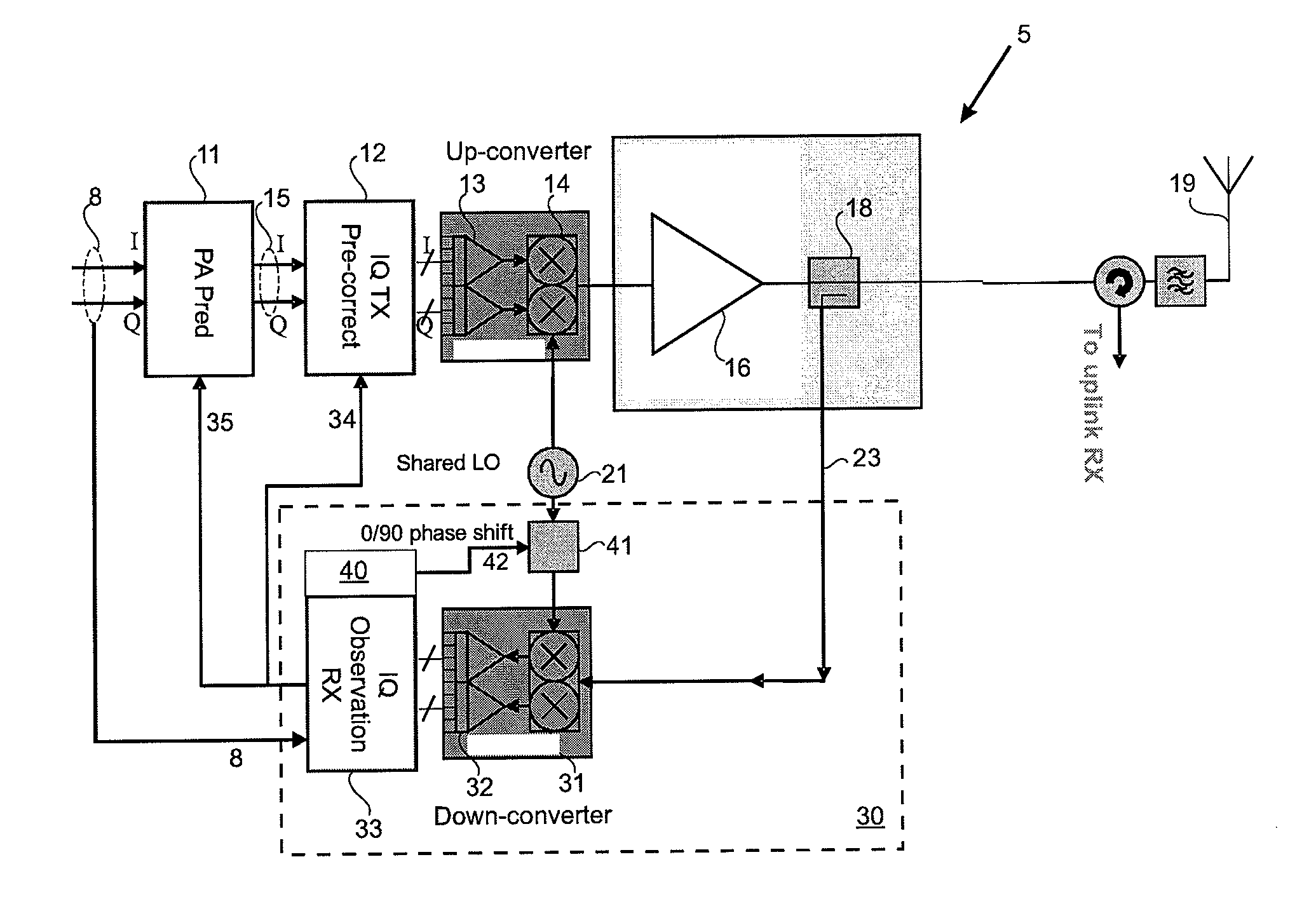
[0031]FIG. 1 shows a first embodiment of a pre-distortion system 5 which can be used as part of the transmit chain of a wireless base station. An input signal 8 is received at an input of a predistortion module 11. The transmit chain uses a quadrature modulation scheme, such as Quadrature Amplitude Modulation (QAM) or Quadrature Phase Shift Keying (QPSK). Accordingly, the input signal 8 representing a digital signal intended for transmission has in-phase (I) and quadrature (Q) components which can subsequently be used to modulate in-phase and quadrature components of a carrier signal. PA Pre-distortion module 11 applies, in the digital domain, pre-distortion to the signal 8 to compensate for expected non-linearities that will be introduced by the power amplifier 16. The pre-distorted signal is applied to an IQ pre-correction module 12 which applies, in the digital domain, a correction to the signal to compensate for expected IQ errors that will be introduced by the up-conversion sta...


PUM


Abstract

A transmit chain comprises a transmit path with a quadrature up-converter which up-converts quadrature signal components to RF. An observation path samples a portion of the RF signal and a quadrature down-converter down-converts the RF signal to baseband quadrature signal components. A local oscillator signal source provides the up-converter and the down-converter with a local oscillator signal and is operable in two states. In a second of the states the local oscillator signal is applied to the up-converter and the down-converter and a phase shift is made to the signal applied to up-converter or the down-converter compared to the first of the states. A processor monitors properties of the down-converted signal while the local oscillator signal source is operating in the first state and the second state. The processor calculates a correction to apply to the baseband observation signal to correct for errors introduced by the observation path. The processor also calculates a correction to apply to the input signal to correct for errors introduced in the transmit path.

Description

FIELD OF THE INVENTION[0001]This invention relates to linearization of systems in which an up-converter and a down-converter both have an IQ architecture. The invention is particularly useful in, but not limited to, the transmit chain of wireless communications devices.BACKGROUND TO THE INVENTION[0002]Wireless communication devices, such as base stations and terminals, have a transmit chain which includes a power amplifier to amplify a modulated signal to a high power level for transmission over a wireless channel. It is known that elements in the transmit chain can introduce distortion to the transmitted signal and therefore there have been various proposals to compensate for distortion. One such proposal is a pre-distortion architecture where a low power modulated signal is pre-distorted in a manner which will compensate for non-linear effects of a power amplifier, before being applied to the input of the power amplifier. The combination of the pre-distortion applied to the input ...

Claims


Application Information

Patent Timeline
Patent Type & Authority Applications(United States)
IPC IPC(8): H04B1/04
CPCH03F1/3247H04B2001/0433H04B2001/0425H03F1/3241H03F1/3294H03F1/34H03F3/24
Inventor ROW, PAULO'FLAHERTY, MARTINDOLMAN, GRAHAM
Owner APPLE INC
Learn More