System for controlling starter for starting internal combustion engine

Active Publication Date: 2010-11-25
DENSO CORP
View PDF8 Cites 110 Cited by
  • Summary
  • Abstract
  • Description
  • Claims
  • Application Information

AI Technical Summary

Benefits of technology

[0017]According to the one aspect of the present invention, the second switch unit is comprised of two-stage relays (first and second relays). That is, because the second relay mainly controls activation of the first relay, it is unnecessary to supply high power to the second relay in ord

Problems solved by technology

The inventors have discovered that there are problems in each of the starter control systems set forth above.
For this reason, because a higher gate current is required to maintain the on state of the second MOS switch, an electronic control circuit, such as a microcomputer, cannot directly control the operations of the second MOS switch.
This results in deteriorating the contr

Method used


Image

  • System for controlling starter for starting internal combustion engine
  • System for controlling starter for starting internal combustion engine
  • System for controlling starter for starting internal combustion engine

Examples


first embodiment

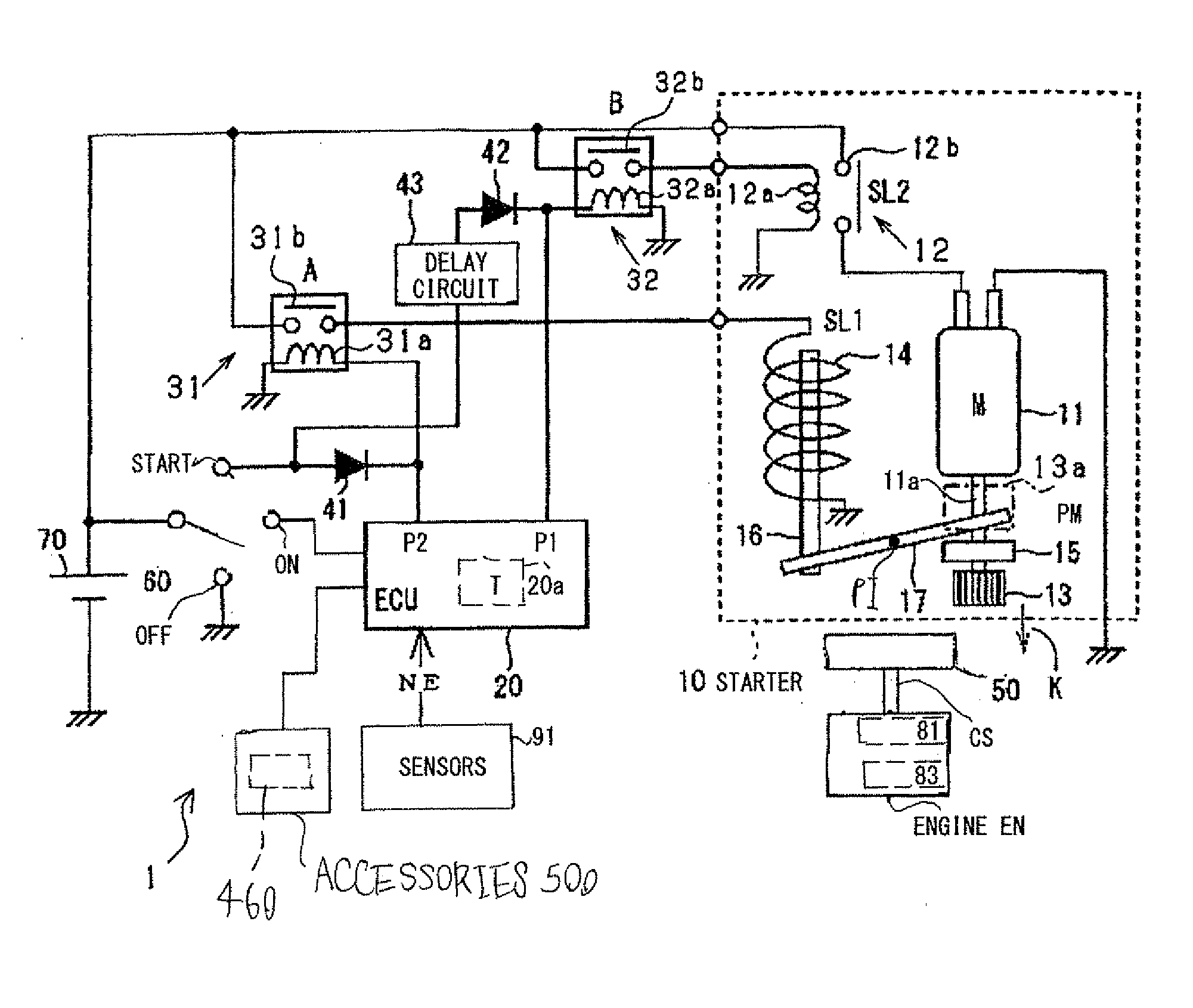
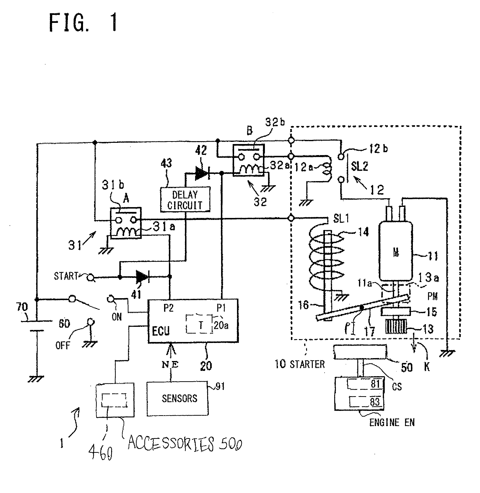
[0034]Referring to FIGS. 1 and 2, an engine starting system 1 according to the first embodiment of the present invention is installed in a motor vehicle. The engine starting system serves as an idle reduction system for automatically controlling the stop and restart of an internal combustion engine (referred to simply as “engine”) EN installed in the motor vehicle.

[0035]The engine starting system 1 is comprised of a starter 10 used to start the engine EN, and an electronic control unit (ECU) 20 for control of operations of the starter 1 at the start of the engine EN. The engine starting system 1 also includes a first drive relay 31, a second drive relay 32, a first diode 41, a second diode 42, a delay circuit 43, and a battery 70.

[0036]Referring to FIG. 1, the engine EN has a crankshaft CS, as an output shaft thereof, with one end to which a ring gear 50 is directly or indirectly coupled.

[0037]The engine EN works to compress air-fuel mixture or air by a moving piston within each cyl...

second embodiment

[0162]An engine starting system 1A according to the second embodiment of the present invention will be described hereinafter with reference to FIG. 3. In FIG. 3, in order to simply illustrate the structure of the engine starting system 1A, the pinion 13, the one-way clutch 15, the plunger 14, the shift lever 17, the engine EN, the sensors 91, and the like are omitted in illustration.

[0163]The structure and / or functions of the engine starting system 1A according to the second embodiment are different from the engine starting system 1 in the following points.

[0164]Specifically, a MOS transistor relay (semiconductor relay) 310 is used, in place of the first drive relay 31, as the first switch unit for energizing and deenergizing the solenoid 14. The drain of the MOS transistor relay 310 is electrically connected to the positive terminal of the battery 70, and the source thereof is electrically connected to the solenoid 14.

[0165]A MOS transistor relay (semiconductor relay) 320 is used, ...

third embodiment

[0178]An engine starting system 1B according to the third embodiment of the present invention will be described hereinafter with reference to FIG. 4. In FIG. 4, in order to simply illustrate the structure of the engine starting system 1B, the pinion 13, the one-way clutch 15, the plunger 14, the shift lever 17, the engine EN, the sensors 91, and the like are omitted in illustration.

[0179]The engine starting system 1A according to the second embodiment is configured to drive the drivers 311 and 321 to output the gate current (energizing current) to the MOS transistor relays 310 and 320 to thereby turn on the MOS transistor relays 310 and 320, respectively.

[0180]At that time, the level of the gate current required to keep each of the MOS transistors 310 and 320 in on state is higher than the level of the energizing current to be supplied to the solenoid of each of the mechanical relays 31 and 32.

[0181]This might not maintain each of the MOS transistors 310 and 320 in on state if the b...


PUM


Abstract

In a system for controlling a starter, the starter includes a pinion shiftable between an engagement position and a disengagement position. The starter includes an actuator configured to shift the pinion from the disengagement position to the engagement position when energized, and a motor configured to rotate the pinion when energized. The system includes a control circuit, a first switch unit configured to switch between energization and deenergization of the actuator under control of the control circuit, and a second switch unit configured to switch between energization and deenergization of the motor under control of the control circuit. The first switch unit and the second switch unit are individually arranged. The second switch unit includes a first relay configured to switch between energization and deenergization of the motor under control of the control circuit, and a second relay configured to control activation of the first relay.

Description

CROSS REFERENCE TO RELATED APPLICATIONS[0001]This application is based on Japanese Patent Application 2009-123207 filed on May 21, 2009. This application claims the benefit of priority from the Japanese Patent Application, so that the descriptions of which are all incorporated herein by reference.FIELD OF THE INVENTION[0002]The present invention relates to systems for controlling starters for starting internal combustion engines.BACKGROUND OF THE INVENTION[0003]Conventional starters for starting internal combustion engines normally include a pinion movable between an engagement position and a disengagement position. When the pinion is located at the engagement position, the pinion is engageable with a ring gear rotatable together with a crankshaft of an internal combustion engine. When the pinion is located at the disengagement position, the pinion is disengaged with the ring gear.[0004]The conventional starters also include an actuator configured to shift the pinion from the engage...

Claims


Application Information

Patent Timeline
IPC IPC(8): F02N11/08
CPCF02N11/087F02N11/0855
Inventor OKUMOTO, KAZUSHIGEKATO, AKIRASENDA, TAKASHI
Owner DENSO CORP
Why Eureka
Try Eureka