Process for producing combustor structural member, and combustor structural member, combustor for gas turbine and gas turbine

Active Publication Date: 2010-12-02
MITSUBISHI POWER LTD
View PDF7 Cites 10 Cited by
  • Summary
  • Abstract
  • Description
  • Claims
  • Application Information

AI Technical Summary

Benefits of technology

[0009]The present invention has been developed in light of the above circumstances, and provides a process for producing a combustor structural member by molding a plate-like assembly having holl

Problems solved by technology

If the heating temperature during brazing is too high, then oxidation and coarsening of the crystal grains of the base metals may occur, resulting in a deterioration in the strength of the base metals.
However, in those cases where this diffusion is insufficient, the melting point lowering element(s) tend to become concentrated on the plate-like members near the above contact surfaces, resulting in localized brittleness.
If a plate-like assembly formed from such plate-like members is subjected to press molding, then cracks may develop

Method used


Image

  • Process for producing combustor structural member, and combustor structural member, combustor for gas turbine and gas turbine
  • Process for producing combustor structural member, and combustor structural member, combustor for gas turbine and gas turbine
  • Process for producing combustor structural member, and combustor structural member, combustor for gas turbine and gas turbine

Examples


Example

[0022]An embodiment of the process for producing a combustor structural member according to the present invention is described below, with reference to the drawings.

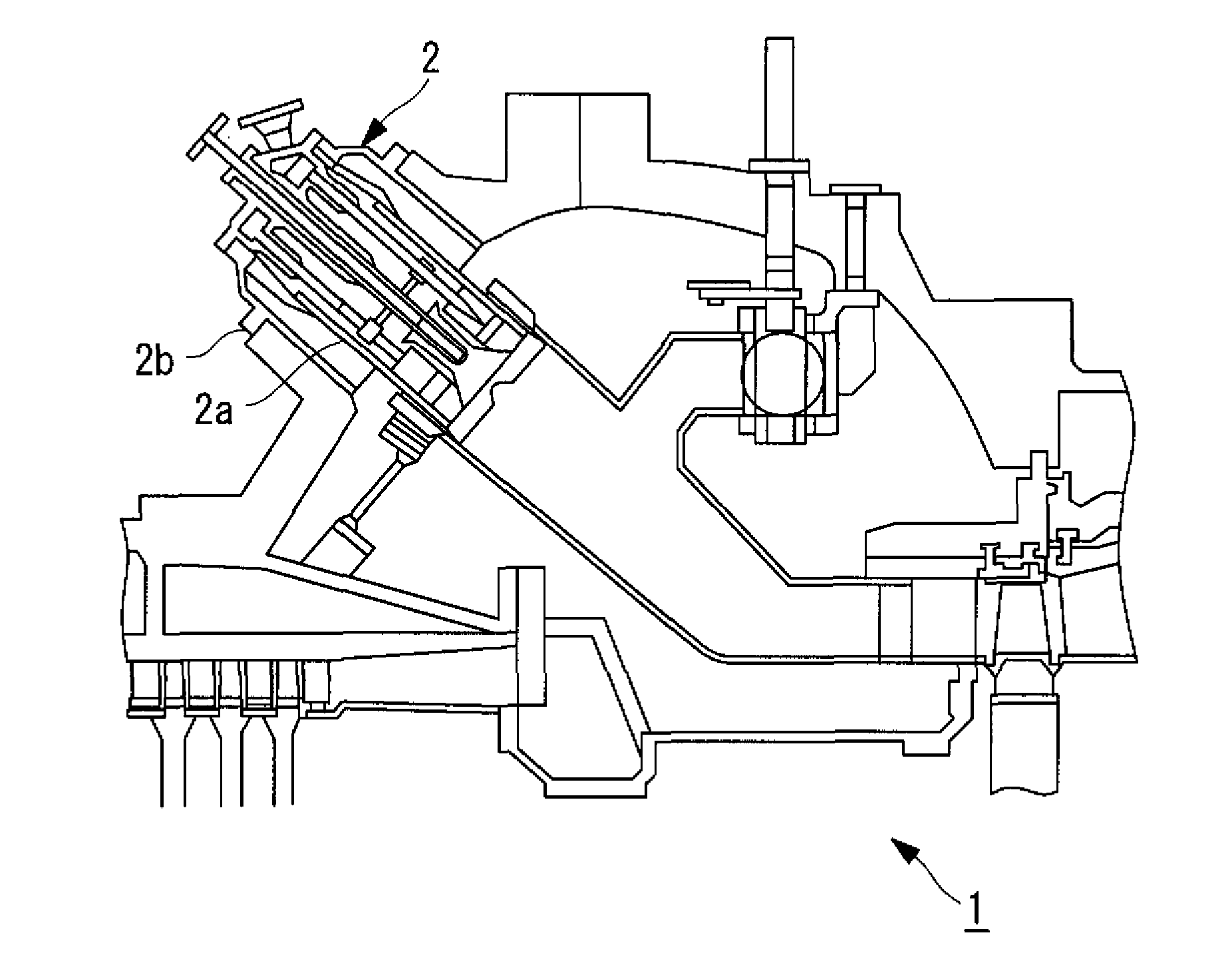
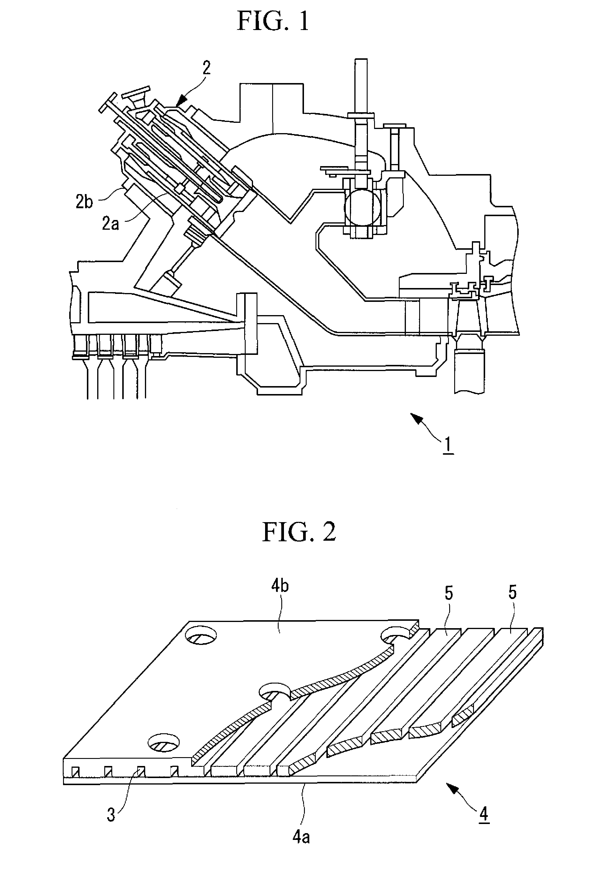
[0023]FIG. 1 illustrates a partial longitudinal sectional view of a gas turbine according to the embodiment. The gas turbine 1 is equipped with a combustor 2 having a combustor basket 2a and an outer cylinder 2b. The combustor basket 2a is produced by provisionally arranging four combustor structural members, and then using laser welding to join the members to form a cylinder. Each of the combustor structural members is obtained by press molding a plate-like assembly having hollow passages formed therein into a predetermined shape. A single combustor structural member has dimensions, for example, within a range from 1.2 m×0.7 m to 1.0 m×0.5 m.

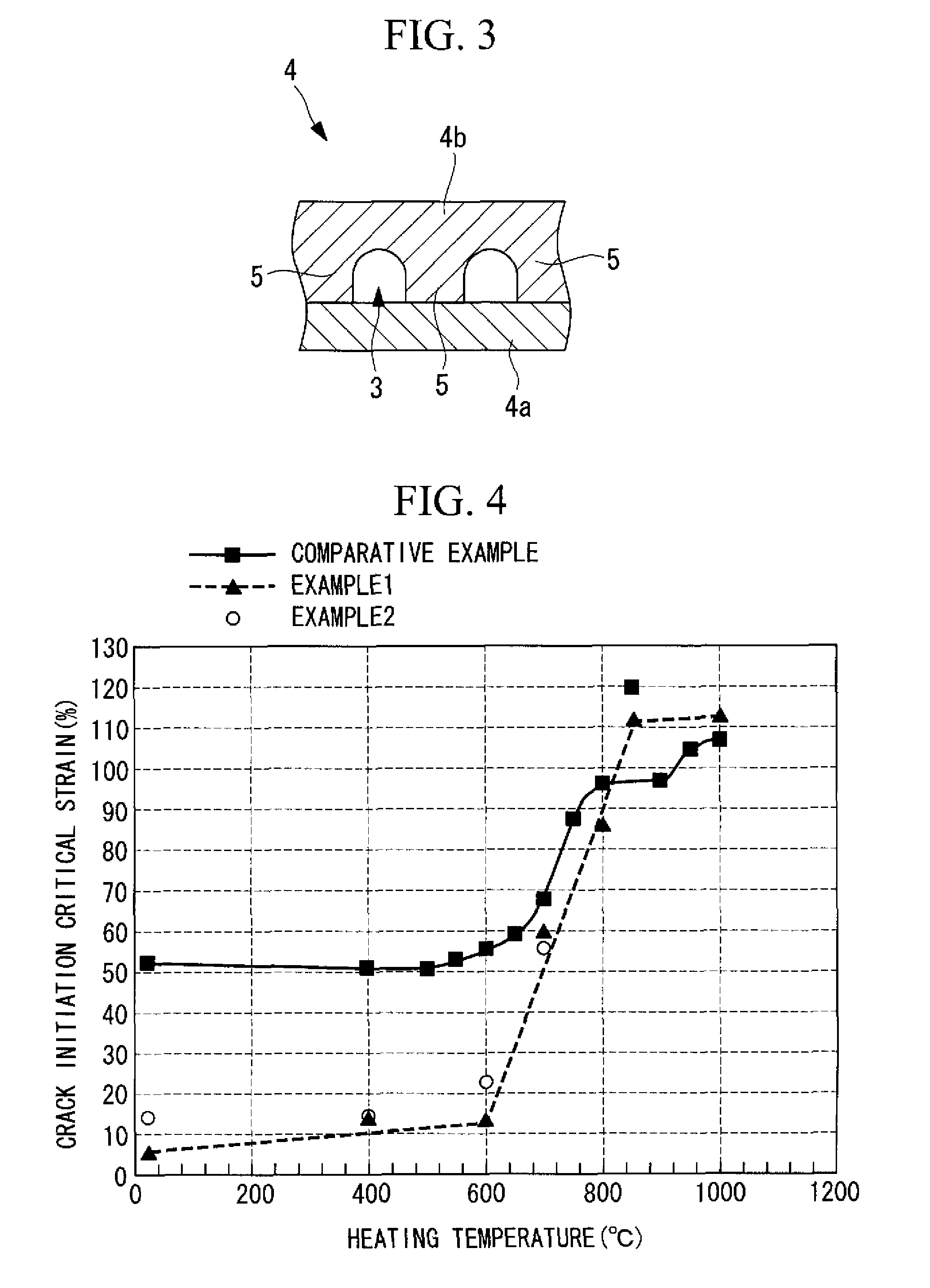
[0024]FIG. 2 shows a perspective view of a plate-like assembly. The plate-like assembly 4 is composed of a first plate-like member 4a having a flat shape, and a second plate-like me...


PUM

PropertyMeasurementUnit
Temperatureaaaaaaaaaa

Abstract

A process for producing a combustor structural member, the process comprising a plate-like assembly formation step of brazing a first plate-like member formed from a heat-resistant alloy, and a second plate-like member formed from a heat-resistant alloy and having a plurality of fins on the surface, with the second plate-like member positioned with the fins facing the first plate-like member, by interposing a brazing filler metal comprising a melting point lowering element between the two plate-like members, thereby forming a plate-like assembly, a press molding step of press molding the plate-like assembly to form a combustor structural member of the desired shape, a strain location identification step of identifying, in accordance with the shape of the combustor structural member, strain locations where the strain generated during the press molding step exceeds a predetermined value, a localized heating step of performing localized heating of the locations within the plate-like assembly corresponding with the strain locations identified in the strain location identification step, and a cold press molding step, which is performed as the above press molding step and comprises subjecting the plate-like assembly to cold press molding with the temperature of the heated locations corresponding with the strain locations maintained at a desired temperature.

Description

CROSS REFERENCE TO RELATED APPLICATION[0001]This application claims benefit of Japanese Patent Application No. 2009-133394 filed in Japan on Jun. 2, 2009, the content of which is incorporated herein by reference.BACKGROUND OF THE INVENTION[0002]1. Field of the Invention[0003]The present invention relates to a process for producing a combustor structural member that can be used (as the combustion liner and combustor basket and the like) within a combustor of a gas turbine.[0004]2. Description of Related Art[0005]Gas turbine combustors are used under high-temperature conditions at approximately 1,500° C. As a result of these operating conditions, such gas turbine combustors require cooling structures. For example, the Publication of Japanese Patent No. 3,831,638 (claim 9 and paragraph [0011]) discloses the use of a plate-like member having hollow passages formed therein, known as an MT fin, as the structural member for the transition piece of a combustor, wherein the gas turbine combu...

Claims


Application Information

Patent Timeline
IPC IPC(8): F02C7/20B21D47/00
CPCB23P15/00B23P2700/13Y10T29/49616F23R2900/00018F23R3/002B21D22/20F01D25/00F02C7/00F23R3/42
Inventor MORIMOTO, HITOSHITANEIKE, MASAKINAGAI, TOMOTO
Owner MITSUBISHI POWER LTD
Why Eureka
Try Eureka