Continuous micro anode guided electroplating device and method thereof

a technology of micro anodes and electroplating devices, which is applied in the direction of electrodes, electrolysis components, cells, etc., can solve the problems of inability to mill, welding and fasten conventional mechanical devices to achieve the space resolution required by microelements, and inability to achieve optimal performance of thickness structures with low aspect ratios. to achieve the effect of reducing the contamination of workpieces

Inactive Publication Date: 2010-12-02
NAT CENT UNIV
View PDF9 Cites 19 Cited by
  • Summary
  • Abstract
  • Description
  • Claims
  • Application Information

AI Technical Summary

Benefits of technology

[0008]Therefore it is a primary object of the present invention to provide a micro anode guided electroplating device and a method thereof in which a workpiece is not soaked in an electrolyte (electroplating solution) so as to reduce the contaminations of the workpiece caused by the electrolyte.

Problems solved by technology

Milling, welding and fastening of conventional mechanical devices haven't achieved the space resolution required by the microelements.
But the uniform thickness structure with low aspect ratio is unable to achieve optimal performance.
However, the deposition rate is not constant so that the micro anode moving in a constant speed will not lead to constant growing of the deposit.
If the micro anode moves too fast, the deposit is gradually reduced in size and finally grows nothing with increasing the distance between the electrodes.
On the contrary, if the micro anode moves too slowly, the deposits contact with the micro anode and a short circuit occurs.
Thus the constant movement of the micro anode is unable to ensure a stable deposit rate.
Thus the deposit is grown in non-uniform size or the electroplating may be interrupted.
Both have affected the quality of electroplated micro components significantly.

Method used


Image

  • Continuous micro anode guided electroplating device and method thereof
  • Continuous micro anode guided electroplating device and method thereof
  • Continuous micro anode guided electroplating device and method thereof

Examples


Embodiment Construction

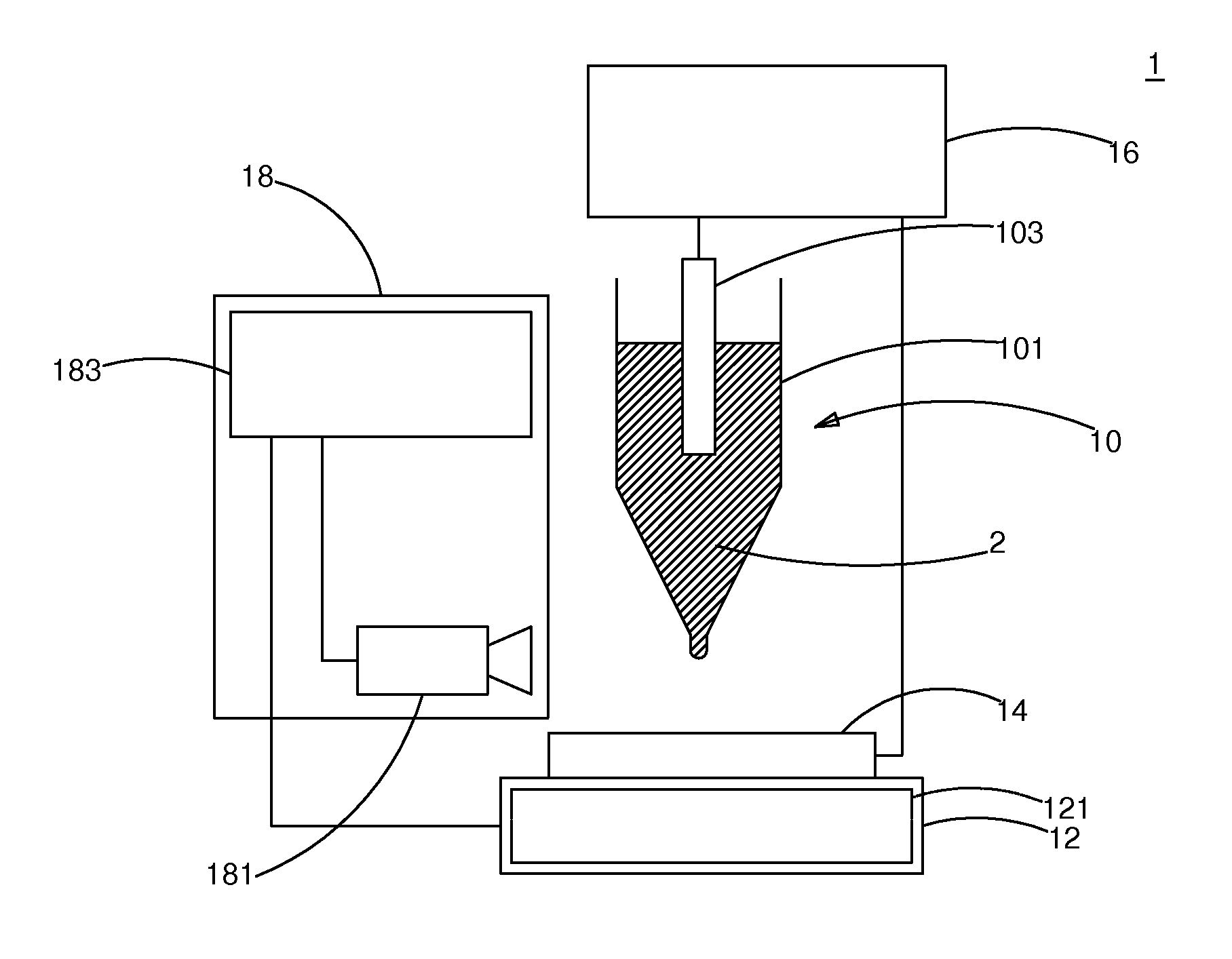
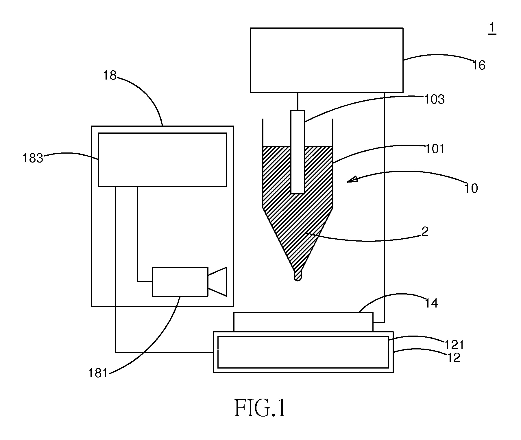
[0017]Refer to FIG. 1, a continuous micro anode guided electroplating device 1 includes a micro anode 1, a loading platform 12, a cathode 14, a power supply 16 and a monitor 18. The micro anode 10 consists of a micro / nanoscale capillary 101 and a conductor 103. The conductor 103 is made from platinum and is disposed inside the capillary 101 that is filled with an electrolyte (electroplating solution) 2. The loading platform 12 is set under the micro anode 10 and is having a driving device 121 therein. The driving device 121 drives the loading platform 12 to move. In this embodiment, the driving device 121 is a motor. The cathode 14 is a workpiece that is put on the loading platform 12 for electroplating. The power supply 16 is composed of an anode and a cathode. The anode of the power supply 16 is connected to the micro anode 10 and the cathode of the power supply 16 is connected to the cathode 14. The power supply 16 supplies a bias to the micro anode 10 and the cathode 14 so that ...


PUM

PropertyMeasurementUnit
distanceaaaaaaaaaa
distanceaaaaaaaaaa
conductoraaaaaaaaaa

Abstract

A continuous micro anode guided electroplating device and a method thereof are revealed. By real-time image monitoring and capillary action of the micro/nanoscale tube, a three-dimensional microstructure is deposited on a workpiece at the cathode. The deposit is growing smoothly under the real-time image monitoring. Moreover, the workpiece is not immersed in an electrolyte so that contaminations of the workpiece caused by electrolyte are reduced.

Description

BACKGROUND OF THE INVENTION[0001]1. Field of Invention[0002]The present invention relates to a micro anode guided electroplating device and a method thereof, especially to a continuous micro anode guided electroplating device and a method thereof.[0003]2. Description of Related Art[0004]Along with fast development of and great advancement in modern technology, the electronic products are getting compact and light weighted. Similarly, the establishment of micromechanical devices provides more benefits. When the mechanical devices are getting smaller, its resonance frequency increases. Thus high bandwidth accelerometers and pressure gauges are produced. The microelements integrate drivers, limbs, sensors, processors and power supplies so as to move around the world under the microscope and applied to medical field.[0005]Milling, welding and fastening of conventional mechanical devices haven't achieved the space resolution required by the microelements. Integrated circuits have been wi...

Claims


Application Information

Patent Timeline
Patent Type & Authority Applications(United States)
IPC IPC(8): C25D21/12C25D17/00
CPCC25D17/00C25D5/02C25D17/10
Inventor LIN, JING-CHIECHANG, TING-KANGYANG, JEN-HUNGHWANG, YEAN-RENCHEN, TING-CHAO
Owner NAT CENT UNIV
Why Eureka
Try Eureka