Frequency synthesizer

a frequency synthesizer and frequency technology, applied in the field of frequency synthesizers, can solve the problem of easy correction errors, and achieve the effect of strengthening variation toleran

Inactive Publication Date: 2010-12-02
RENESAS ELECTRONICS CORP
View PDF6 Cites 26 Cited by
  • Summary
  • Abstract
  • Description
  • Claims
  • Application Information

AI Technical Summary

Benefits of technology

[0026]According to the present invention, it is possible to provide a frequency synthesizer that streng...

Problems solved by technology

However, since the capacitor bank setting differs even for th...

Method used


Image

  • Frequency synthesizer
  • Frequency synthesizer
  • Frequency synthesizer

Examples


second exemplary embodiment

[0088]FIG. 10 is a diagram showing a configuration of a second exemplary embodiment of a frequency synthesizer of the present invention. In the present exemplary embodiment, as shown in FIG. 10, with a control signal bit=0, bit=N, of a VCO capacitor bank, ON and OFF states of a switch of a parallel resistor array 75 of a temperature compensation block 7 are controlled at the same time. In this way; a resistance value corresponding to each capacitance bit is given a weighting. A variable resistor 76 that responds to an output voltage of a correction potential generation circuit 73 of a varactor is provided. The variable resistor 76 and the parallel resistor array 75 are combined and a correction potential 25 is adjusted as a voltage dividing resistance value.

third exemplary embodiment

[0089]FIG. 11 is a diagram showing a configuration of a third exemplary embodiment of a frequency synthesizer of the present invention. In the present exemplary embodiment, a series resistor array 77 of a temperature compensation block 7 is controlled by a control signal of a VCO capacitor bank. In this way, a resistance value corresponding to each capacitance bit is given a weighting. A variable resistor 76 that responds to an output voltage of a correction potential generation circuit 71 of a varactor is provided. When bit=0 is “1”, the series resistor array 77 skips a resistor.

fourth exemplary embodiment

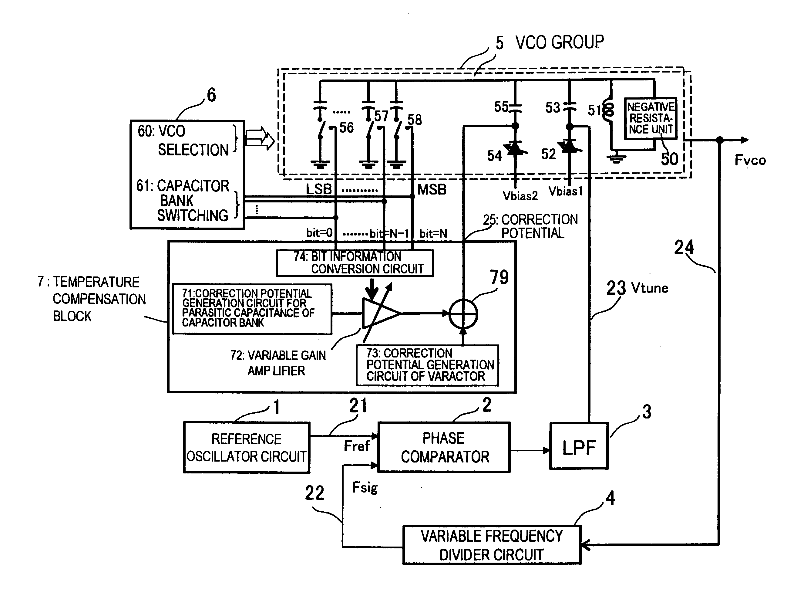
[0090]FIG. 12 is a diagram showing a configuration of a fourth exemplary embodiment of a frequency synthesizer of the present invention. A correction potential generation circuit 71 for a parasitic capacitance of a capacitor bank doubles as a reference voltage generator of a DAC (digital analog converter) 78. Therefore, a DAC output voltage has a temperature characteristic similar to a reference voltage, and an absolute value thereof is controlled by control information (bit=0, . . . bit=N) of a VCO capacitor bank. An output voltage of a correction potential generation circuit 73 of a varactor is added to the output voltage of the DAC 78 by an adder circuit 79, to obtain a correction potential 25.


PUM


Abstract

A frequency synthesizer comprises a VCO group; a phase comparator; and a loop filter. Each VCO includes a varactor and a capacitor bank including a plurality of weighted capacitance elements, and a plurality of switches turned ON and OFF based on a control signal. Also provided a temperature compensation including a varactor correction potential generation circuit, a correction potential generation circuit for parasitic capacitance of the capacitor bank, a variable gain amplifier in which weighting processing, based on a control signal of the capacitor bank, is performed on an output potential of the correction potential generation circuit, and an adder circuit that adds the output voltage of the correction potential generation circuit of the varactor and output voltage of the variable gain amplifier, and the varactor of the VCO is controlled by output (correction potential) of the adder circuit.

Description

TECHNICAL FIELDReference to Related Application[0001]This application is based upon and claims the benefit of the priority of Japanese patent application No. 2009-126056, filed on May 26, 2009, the disclosure of which is incorporated herein in its entirety by reference thereto.[0002]The present invention relates to a frequency synthesizer, and in particular to a frequency synthesizer using a PLL (Phase Locked Loop).BACKGROUND[0003]In wireless communication equipments, tuners, and so forth, a frequency synthesizer using a PLL (also referred to as a PLL synthesizer, or simply a PLL) is widely used. FIG. 1 is a diagram showing one example of a typical configuration of a frequency synthesizer. Referring to FIG. 1, the frequency synthesize includes a VCO (Voltage Controlled Oscillator) group 5, a frequency divider circuit (variable frequency divider circuit) 4 that frequency-divides a VCO output 24 (frequency Fvco), a phase comparator 2 that detects a phase difference between a signal (f...

Claims


Application Information

Patent Timeline
IPC IPC(8): H03L7/08
CPCH03L1/022H03L2207/06H03L7/18H03L7/099
Inventor HU, WEILIANGMATSUNO, NORIAKI
Owner RENESAS ELECTRONICS CORP
Why Eureka
Try Eureka