

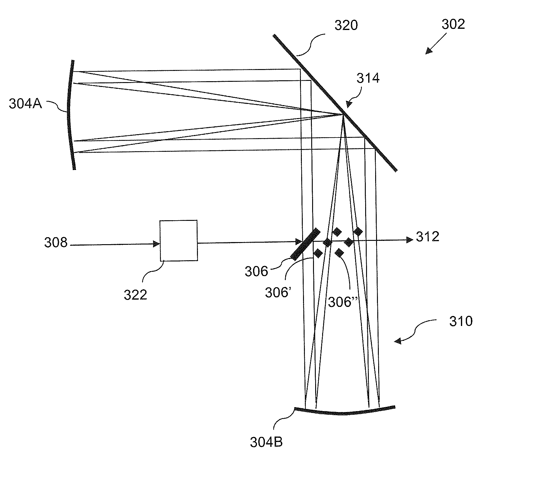
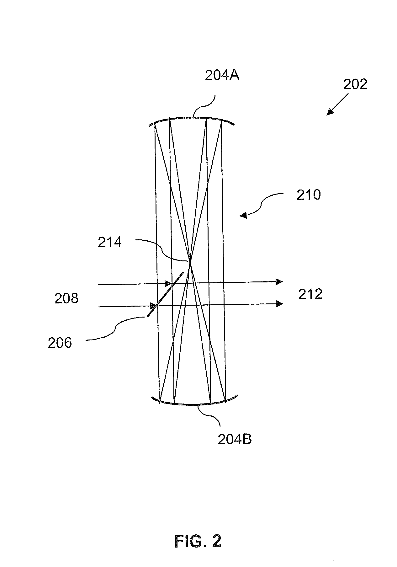
Pulse Stretcher with Reduced Energy Density on Optical Components
a technology of optical components and stretchers, applied in the field of optical pulse stretching systems and methods, can solve the problems of optical damage known to increase, large cost of expensive lens elements that are difficult to fabricate, and difficult to fabricate large-scale lithographic equipment, etc., and achieve the effect of reducing or preventing optic damage and high efficiency
- Summary
- Abstract
- Description
- Claims
- Application Information
AI Technical Summary
Benefits of technology
Problems solved by technology
Method used
Image

Examples
Embodiment Construction
[0031]The disclosed embodiments merely exemplify the invention. The scope of the invention is not limited to the disclosed embodiments. The invention is defined by the claims appended hereto.
[0032]The embodiments described, and references in the specification to “one embodiment”, “an embodiment”, “an example embodiment”, etc., indicate that the embodiments described may include a particular feature, structure, or characteristic, but every embodiment may not necessarily include the particular feature, structure, or characteristic. Moreover, such phrases are not necessarily referring to the same embodiment. Further, when a particular feature, structure, or characteristic is described in connection with an embodiment, it is understood that it is within the knowledge of one skilled in the art to effect such feature, structure, or characteristic in connection with other embodiments whether or not explicitly described.
[0033]Embodiments of the invention may be implemented in hardware, firm...
PUM
| Property | Measurement | Unit |
|---|---|---|
| pulse power | aaaaa | aaaaa |
| power | aaaaa | aaaaa |
| angle | aaaaa | aaaaa |
Abstract
Description
Claims
Application Information