Mopa light source

Inactive Publication Date: 2010-12-02
MEGAOPTO
View PDF15 Cites 15 Cited by
  • Summary
  • Abstract
  • Description
  • Claims
  • Application Information

AI Technical Summary

Benefits of technology

[0016]The present invention has been developed to eliminate the problems described above. It is an object of the present invention to provide a MOPA light source which uses an optical fiber amplifier to amplify light from pulse oscilla

Problems solved by technology

In a MOPA light source which performs wavelength conversion using a nonlinear optical crystal, there is the concern that the nonlinear optical crystal may be damaged.
As a result, there are the problems of difficulty of connection and increased costs.
Consequently, the need arises to use a LMA (Large-Mode-Area) fiber, connection and accommodation of which are difficult.
On the other han

Method used


Image

  • Mopa light source
  • Mopa light source
  • Mopa light source

Examples


Example

[0033]In the following, embodiments of a MOPA light source according to the present invention will be explained in detail with reference to FIGS. 3-8, 9A-9E, 10-11, and 12A-12G. In the description of the drawings, identical or corresponding components are designated by the same reference numerals, and overlapping description is omitted.

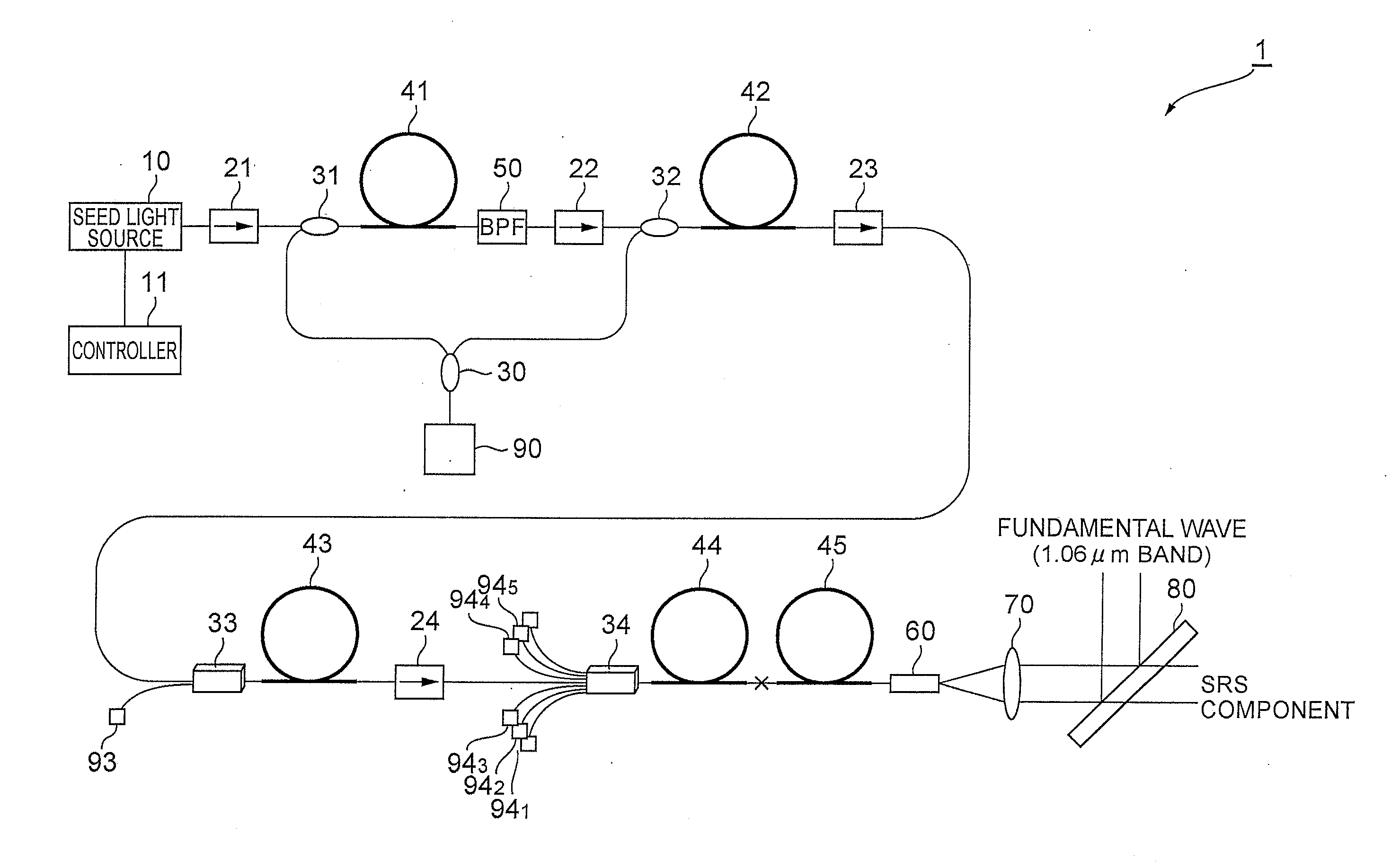
[0034]FIG. 3 is a view showing a configuration of an embodiment of a MOPA light source according to the present invention. The MOPA light source 1, shown in FIG. 3, comprises a seed light source 10, a controller 11, optical isolators 21 to 24, optical couplers 30 to 32, combiners 33 and 34, amplification optical fibers 41 to 44, a passive optical fiber 45, a band-pass filter 50, an end cap 60, a lens 70, a branching filter 80, and pumping light sources 90, 93, 941 through 945.

[0035]The seed light source 10 generates pulsed light serving as fundamental light wave. It is preferable that the seed light source 10 have an optical amplification waveguide do...


PUM


Abstract

The present invention relates to a MOPA light source capable of obtaining pulse output by wavelength-conversion of pulse light of fundamental light wave using a simple configuration, and suppressing optical output using a simple method when processing is not performed. The fundamental light wave outputted from a seed light source is amplified in an optical amplification fiber. The amplified fundamental light wave is inputted to one end of a passive optical fiber, and propagates in the passive optical fiber. In the passive optical fiber, stimulated Raman scattering occurs upon propagation of the fundamental light wave. The light of fundamental light wave and light of stimulated Raman-scattered components are outputted from the other end of the passive optical fiber. The light outputted from the passive optical fiber is collimated by a lens, and is then inputted to a branching filter. The light inputted to the branching filter is wavelength-separated into light of stimulated Raman-scattered components having wavelengths longer than that of the fundamental light wave, and light having wavelengths equal to or less than that of the fundamental light wave.

Description

BACKGROUND OF THE INVENTION[0001]1. Field of the Invention[0002]The present invention relates to a Master Oscillator Power Amplifier (MOPA) light source.[0003]2. Related Background of the Invention[0004]A MOPA light source employs an optical amplifier to amplify seed light outputted from a seed light source, and outputs the amplified light. For example, a semiconductor laser is used as a seed light source, and an optical fiber amplifier is used as an optical amplifier.[0005]Such a MOPA light source has a high degree of freedom of various conditions, such as the pulse width of output light and the repetition frequency, and so is attracting attention as a pulsed light source for laser processing, optical measurement, and various other applications. In the MOPA light source, the pulse period is not limited by the device hardware structure, as in mode-locked designs.[0006]A MOPA light source having such characteristics is used in fine laser processing and other applications. In this cas...

Claims


Application Information

Patent Timeline
IPC IPC(8): H01S3/30
CPCH01S3/06758H01S3/094061H01S3/09408H01S3/10023H01S3/1618H01S3/2316H01S3/302
Inventor KAKUI, MOTOKI
Owner MEGAOPTO
Why Eureka
Try Eureka