Dc-dc converter

a dc-dc converter and converter technology, applied in the direction of electric variable regulation, process and machine control, instruments, etc., can solve the problems of large loss, abnormal oscillation etc., to prevent abnormal oscillation without increasing the gain of the photocoupler, deterioration of efficiency, and prevent abnormal oscillation.

Active Publication Date: 2010-12-02
SANKEN ELECTRIC CO LTD
View PDF2 Cites 11 Cited by
  • Summary
  • Abstract
  • Description
  • Claims
  • Application Information

AI Technical Summary

Benefits of technology

[0019]The DC-DC converter of the related art prevents a voltage increase under light load by increasing the gain of the photocoupler up to a maximum stable limit. When the DC-DC converter is mass-produced, parts variations among the mass-produced products or temperature changes will trigger the abnormal oscillation. There is an idea of providing the DC-DC converter with a dummy load corresponding to a light load to start a sharp frequency increase, to prevent the abnormal oscillation without increasing the gain of the photocoupler. According to the data of FIG. 4, a dummy load of 0.01% of a rated load will be sufficient. The dummy load, however, causes a large loss and deteriorates efficiency.

Problems solved by technology

When the DC-DC converter is mass-produced, parts variations among the mass-produced products or temperature changes will trigger the abnormal oscillation.
The dummy load, however, causes a large loss and deteriorates efficiency.

Method used


Image

  • Dc-dc converter
  • Dc-dc converter
  • Dc-dc converter

Examples


embodiment 1

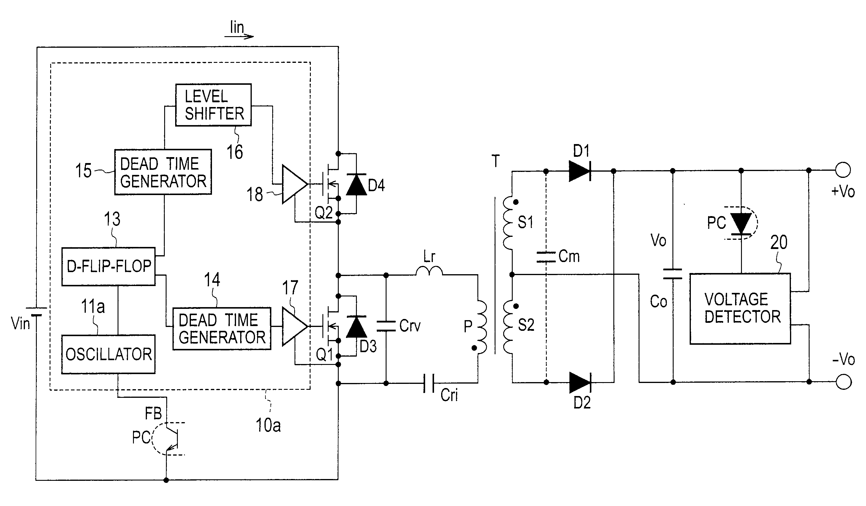
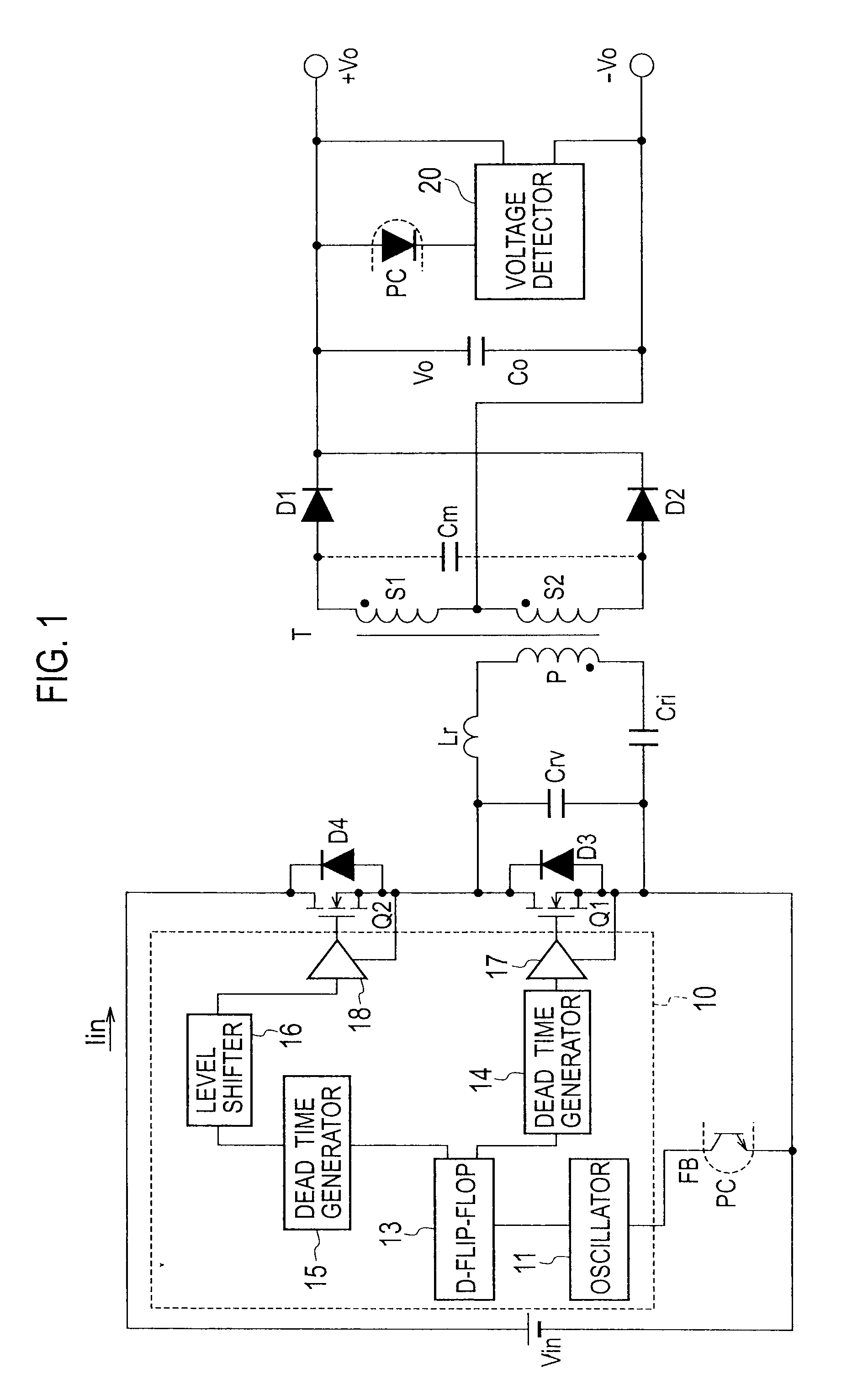
[0034]FIG. 6 is a circuit diagram illustrating a DC-DC converter according to Embodiment 1 of the present invention. In FIG. 6, both ends of a DC power source Vin are connected to a series circuit including switch elements Q1 and Q2 each of a MOSFET. Connected between drain and source of the switch element Q1 is a diode D3 and connected between drain and source of the switch element Q2 is a diode D4. The diodes D3 and D4 may be parasitic diodes of the switch elements Q1 and Q2. Between the drain and source of the switch element Q1, there are connected a series circuit including a reactor Lr, a primary winding P of a transformer T, and a current resonant capacitor Cri, as well as a voltage resonant capacitor Crv.

[0035]Secondary windings S1 and S2 of the transformer T are connected in series. A first end of the secondary winding S1 is connected to an anode of a Diode D1. A first end of the secondary winding S2 is connected to an anode of a diode D2. Cathodes of the diodes D1 and D2 ar...

embodiment 2

[0046]FIG. 8 is a circuit diagram illustrating a DC-DC converter according to Embodiment 2 of the present invention. The DC-DC converter of Embodiment 2 employs as the nonlinear response unit an oscillator 11b and a logarithmic converter 12, instead of the oscillator 11a of Embodiment 1. The remaining configuration of Embodiment 2 is the same as that of Embodiment 1, and therefore, the oscillator 11b and logarithmic converter 12 will mainly be explained.

[0047]FIG. 9 is a circuit diagram illustrating the logarithmic converter 12 and oscillator 11b contained in a controller 10b of the DC-DC converter according to the present embodiment.

[0048]As illustrated in FIG. 10, the logarithmic converter 12 converts a feedback voltage FB (input voltage) from a photocoupler PC into a logarithmic voltage (a voltage that nonlinearly changes) and outputs the converted voltage as an output voltage to the oscillator 11b. The logarithmic converter 12 has a logarithmic characteristic illustrated in FIG....


PUM


Abstract

A DC-DC converter includes a plurality of switch elements connected in series between both ends of a DC power source, a series circuit of a primary winding of a transformer and a capacitor, connected between a connection point of the plurality of switch elements and an end of the DC power source, a rectifying-smoothing circuit to rectify and smooth a voltage generated by a secondary winding of the transformer into a DC voltage, and a controller to change a switching frequency of the plurality of switch elements according to a feedback signal generated from the DC voltage and alternately turn on/off the plurality of switch elements. The controller includes a nonlinear response unit 11a to nonlinearly change the switching frequency according to a feedback amount represented by the feedback signal.

Description

BACKGROUND OF THE INVENTION[0001]1. Field of the Invention[0002]The present invention relates to a DC-DC converter, and particularly, to feedback control of the DC-DC converter.[0003]2. Description of the Related Art[0004]FIG. 1 is a circuit diagram illustrating a DC-DC converter according to a related art. Operation of the DC-DC converter of FIG. 1 will be explained. A DC power source Vin applies a voltage to a starter (not illustrated) to start a controller 10. The controller 10 has an oscillator 11, a D-flip-flop 13, dead time generators 14 and 15, a level shifter 16, and buffers 17 and 18, to alternately turn on / off switch elements Q1 and Q2 with a dead time included.[0005]When the switch element Q2 is turned on, a current passes clockwise through a path extending along Vin, Q2, Lr, P, Cri, and Vin. This current is a resultant current of an excitation current passing through an excitation inductance Lp on the primary side of a transformer T and a load current supplied through a ...

Claims


Application Information

Patent Timeline
Patent Type & Authority Applications(United States)
IPC IPC(8): H02M3/335
CPCH02M3/3376H02M2001/0058Y02B70/1491Y02B70/10H02M1/0058
Inventor USUI, HIROSHI
Owner SANKEN ELECTRIC CO LTD
Why Eureka
Try Eureka