Integrated contaminant6 separator and water-control loop for a fuel reactant stream

a technology of contaminant6 and separator, which is applied in the field of fuel cells, can solve the problems of frequent containment of contaminants, ammonia in the reformate fuel stream affecting the performance of the fuel cell, and fuel cells that include phosphoric acid as an electrolyte cannot achieve the desired 10 year li

Active Publication Date: 2010-12-02
INT FUEL CELLS
View PDF10 Cites 5 Cited by
  • Summary
  • Abstract
  • Description
  • Claims
  • Application Information

AI Technical Summary

Benefits of technology

[0006]The disclosure is directed to an integrated contaminant separator and water-control loop for a fuel reactant stream of a fuel cell. The integrated contaminant separator is a separator scrubber secured in fluid communication with a fuel reactant inlet line of the fuel cell. The scrubber includes a packed bed of high surface area medium disbursed within a scrubber container. A water discharge is secured above the packed bed for discharging water to flow by gravity over the surface area of the medium. A fuel reactant discharge is secured below the packed bed for discharging the fuel reactant to flow upward from the fuel reactant discharge through the packed bed. An accumulator is secured in fluid communication...

Problems solved by technology

Unfortunately, such reformate fuels frequently contain contaminants especially ammonia.
The presence of ammonia in the reformate fuel stream is detrimental to the performance of the fuel cell.
Known fuel cells that include phosphoric acid as an electrolyte cannot achieve a desired 10 year life with greater than 1-2 percent nitrogen within the natural gas.
Although effective, the system of Grasso requires complex and costly strippers and processing of a large volume of fuel cell coolant water.
Again, while effective the Bonville, Jr. et ...

Method used


Image

  • Integrated contaminant6 separator and water-control loop for a fuel reactant stream
  • Integrated contaminant6 separator and water-control loop for a fuel reactant stream
  • Integrated contaminant6 separator and water-control loop for a fuel reactant stream

Examples


Embodiment Construction

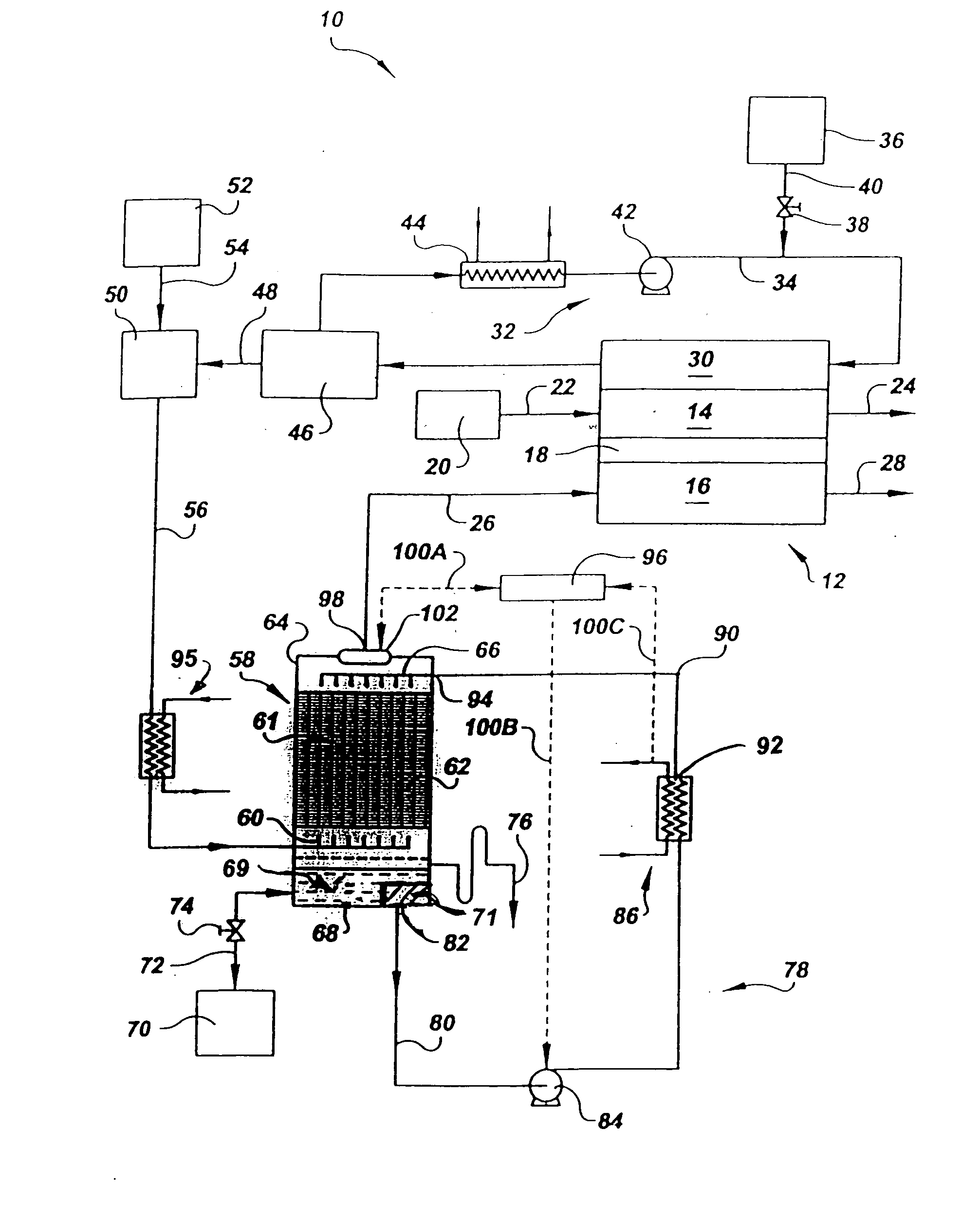
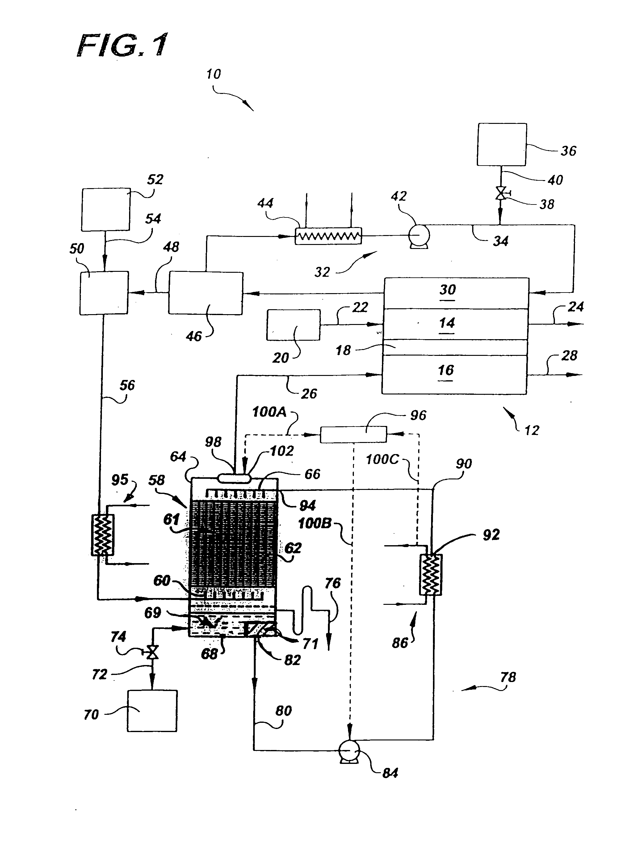
[0017]Referring to the drawings in detail, an integrated contaminant separator and water-control loop for a fuel reactant stream of a fuel cell is shown in FIG. 1 and is generally designated by the reference numeral 10. A fuel cell 12 appropriate for the present disclosure includes a cathode flow field 14 and an anode flow field 16 secured to apposed sides of an electrolyte 18. The electrolyte 18 may be a phosphoric acid electrolyte, a proton exchange membrane (“PEM”) electrolyte, or any electrolyte known in the art. An oxygen supply 20 delivers an oxygen containing reactant stream through an oxidant inlet 22 into and through the cathode flow field 14, and the oxygen reactant stream leaves the fuel cell 12 through a cathode vent 24. A hydrogen containing reducing fluid fuel is directed to flow through a fuel reactant inlet line 26 through the anode flow field 16 and out of the fuel cell 12 through anode vent 28.

[0018]The fuel cell 12 may also include a coolant plate 30 that has a wa...


PUM

PropertyMeasurementUnit
Timeaaaaaaaaaa
Volumeaaaaaaaaaa
Solubility (mass)aaaaaaaaaa

Abstract

An integrated contaminant separator and water-control loop (10) decontaminates a fuel reactant stream of a fuel cell (12). Water passes over surfaces of an ammonia dissolving means (61) within a separator scrubber (58) while the fuel reactant stream simultaneously passes over the surfaces to dissolve contaminants from the fuel reactant stream into the water. An accumulator (68) collects the separated contaminant stream, and ion exchange material (69) integrated within the accumulator removes contaminants from the stream. A water-control pump (84) directs flow of a de-contaminated water stream from the accumulator (68) through a water-control loop (78) having a heat exchanger (86) and back onto the scrubber (58) to flow over the packed bed (62). Separating contaminants from the fuel reactant stream and then isolating and concentrating the separated contaminants within the ion exchange material (69) minimizes cost and maintenance requirements.

Description

TECHNICAL FIELD[0001]The present disclosure relates to fuel cells that are suited for usage in transportation vehicles, portable power plants, or as stationary power plants, and the disclosure especially relates to a contaminant removal system for efficiently removing contaminants such as ammonia from a fuel reactant stream passing into a fuel cell.BACKGROUND ART[0002]Fuel cells are well known and are commonly used to produce electrical current from hydrogen containing reducing fluid fuel and oxygen containing oxidant reactant streams to power electrical apparatus such as transportation vehicles. In fuel cells of the prior art, it is well known that fuel is produced by a reformer and the resulting fuel is referred to as a reformate fuel that flows from the reformer through a fuel reactant stream inlet line into an anode flow field of the fuel cell. As is well known an oxygen rich reactant simultaneously flows through a cathode flow field of the fuel cell to produce electricity. Unfo...

Claims


Application Information

Patent Timeline
IPC IPC(8): H01M8/06
CPCH01M8/04119H01M8/0662H01M8/086H01M2008/1095Y02E60/50
Inventor LINES, MICHAEL T.HILDRETH, DEREK W.PRESTON, JOHN L.
Owner INT FUEL CELLS
Why Eureka
Try Eureka