Dental Implant System and Method of Use

Inactive Publication Date: 2010-12-02
LAYTON GRANT H
View PDF26 Cites 66 Cited by
  • Summary
  • Abstract
  • Description
  • Claims
  • Application Information

AI Technical Summary

Benefits of technology

[0032]The invention also relates to a computer-readable medium that carries one or more sequences of instructions for digital imaging and design of a dental implant system, and for providing instructions to a dental CAD/CAM milling machine. In one embodiment, execution of the sequences of instructions generates an analysis of surface and X-ray data provided by integration software that produces a digital model of a jaw of the patient, and the development of contour data both for the implant and for the abutment

Problems solved by technology

1. Metal implants are mostly made not from pure titanium, but from titanium alloys to improve ease of machining. For example, Grade 5 titanium is sometime employed, which is an alloy that contains aluminum and vanadium. Some of those titanium alloys contain elements that are potentially toxic elements.
2. Metal implants may cause “oral galvanism,” which is a toxic effect caused by a galvanic current generated from the transport of metal ions through the saliva from the implant to another metallic restoration such as a different implant, a filling, a crown or an orthodontic device. As a consequence, the rate of corrosion (or dissolution) of a metal-based restoration is increased, leading to dispersion of metal ions and related oxides in the patient's body and to sensitivity, inflammations, allergies and autoimmune diseases.
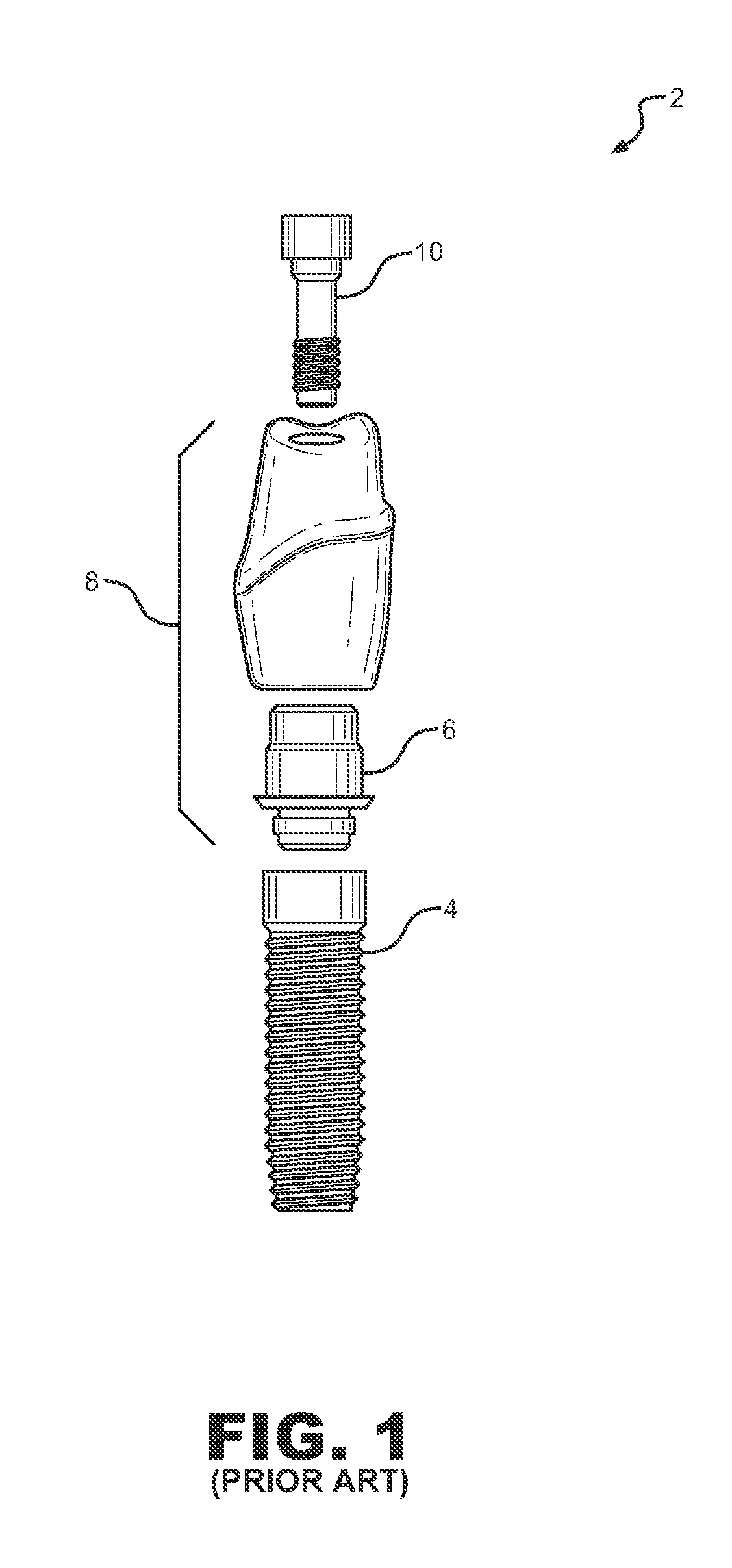
3. The attachment of the internal screw (for example, screw 10 of FIG. 1) may fail. The screw may loosen, break, and become a source of bacteria due to manufacturing tolerances between the screw and the implant, leading to a rejection or to a supporting bone failure for the entire implant.
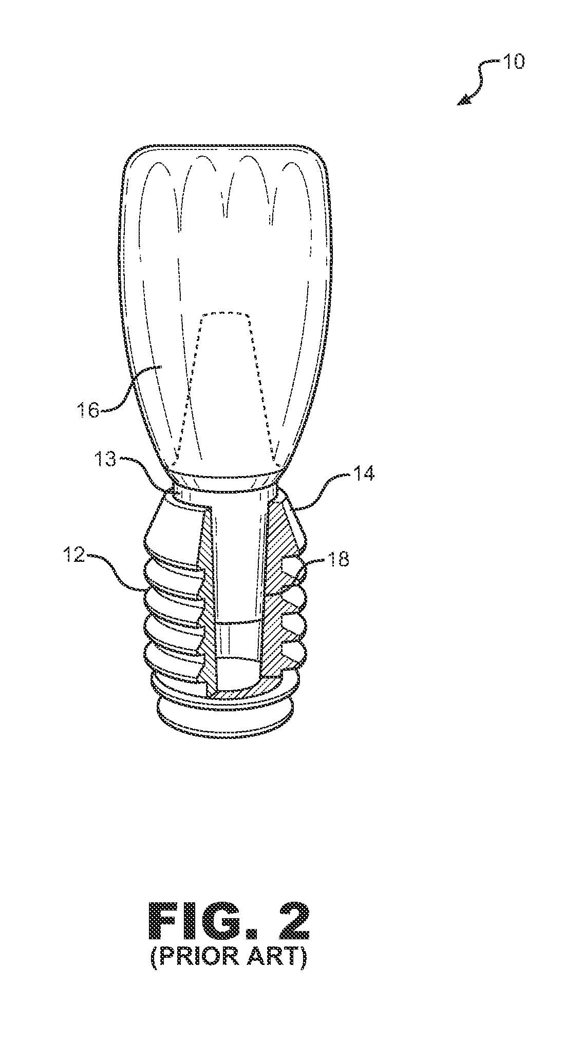
4. Current implant designs include a number of curvatures and recesses that may house bacterial colonies and cause infections and inflammations for lack of access and proper dental hygiene.
5.

Method used


Image

  • Dental Implant System and Method of Use
  • Dental Implant System and Method of Use
  • Dental Implant System and Method of Use

Examples


Example

[0051]Detailed descriptions of embodiments of the invention are provided herein. It is to be understood, however, that the present invention may be embodied in various forms. Therefore, the specific details disclosed herein are not to be interpreted as limiting, but rather as a representative basis for teaching one skilled in the art how to employ the present invention in virtually any detailed system, structure, or manner.

[0052]Referring first to FIG. 3, an implant system according to the principles of the invention includes an implant 20 and an abutment 22. Both implant 20 and abutment 22 are made from a millable ceramic such as zirconia. “Made from a millable ceramic” is meant to describe a product made from a pure form of the millable ceramic (for example, from pure zirconia) or from a composition containing the millable ceramic. For the sake of brevity, the embodiments described hereinafter will be disclosed using zirconia as the millable ceramic. Zirconia implant systems offer...


PUM


Abstract

A dental implant system includes an implant having a well and an abutment having a post shaped to be received in the tapered well. Both the implant and the abutment are made from a millable ceramic, and the abutment post and/or the implant well have grooves carved therein. In one embodiment, the implant and the abutment are joined one to the other with a retentive elastomeric product containing micro-bubbles and micro-spacers. The dental implant system may be produced using a computer-readable medium containing instructions for analyzing surface data and X-ray data, for developing contour data of the implant and of the abutment according to the anatomy of the patient, and for generating machine instruction for milling the implant and the abutment from blocks of the millable ceramic. The invention provides the dentist with total flexibility in determining the most appropriate contours of the implant system and in reducing inventory.

Description

FIELD OF THE INVENTION[0001]The present invention concerns a dental implant system made from a millable ceramic material and related methods of use. More particularly, the present invention concerns a dental implant system, in which an implant having a well engages an abutment having a post and a collar that extends outwardly to be flush with the outer surface of the implant. In one embodiment, the implant and the abutment are joined one to the other with a retentive elastomeric product, which contains micro-bubbles and spacer elements and which fills grooves provided on the abutment post and / or the implant well.BACKGROUND OF THE INVENTION[0002]A dental implant system is an artificial tooth root replacement, which is used in prosthetic dentistry to support restorations that resemble a tooth or a group of teeth. An implant system typically includes an implant or base, which is surgically placed in the jaw of a patient, and an abutment or extension, which extends from the implant to s...

Claims


Application Information

Patent Timeline
IPC IPC(8): A61C8/00A61C13/08
CPCA61C8/005A61C8/0056A61C13/0003A61C13/0004A61C8/0069
Inventor LAYTON, GRANT H.
Owner LAYTON GRANT H
Why Eureka
Try Eureka