Heaving ocean wave energy converter

a wave energy converter and wave energy technology, applied in the direction of electric generator control, machines/engines, mechanical equipment, etc., can solve the problems of low wave energy capture efficiency, few commercial owec deployments, and high cost per average unit of energy captur

Inactive Publication Date: 2010-12-09
ROHRER TECH
View PDF4 Cites 87 Cited by
  • Summary
  • Abstract
  • Description
  • Claims
  • Application Information

AI Technical Summary

Problems solved by technology

Inexpensive fossil fueled and hydroelectric power, however, has resulted in few commercial OWEC deployments.
Less than a dozen OWEC designs are currently deployed as “commercial proto-types.” Virtually all of these suffer from high cost per average unit of energy capture.
This is primarily due to the use of heavy steel construction necessary for severe sea-state survivability combined with (and in part causing) low wave energy capture efficiency.
Most subsurface OWECs are, unfortunately, designed for near shore sea bed deployment.
Ocean waves lose a substantial portion of their energy as they approach shore (due to breaking, reflected waves, and bottom hydrodynamic friction effects).
Near shore, submerged sea bed OWECs must be deployed at greater depths relative to average wave trough depths due to severe sea-state considerations to avoid breaking wave turbulence, and depth can not be adjusted for the large tidal depth variations found at the higher latitudes where average wave heights are greatest.
All of the prior subsurface deformable container OWECs suffer from high moving mass (and therefore cost) and low energy capture efficiency often due to such high moving mass (even more cost) or due to near shore or sea bed deployment.

Method used


Image

  • Heaving ocean wave energy converter
  • Heaving ocean wave energy converter
  • Heaving ocean wave energy converter

Examples


Embodiment Construction

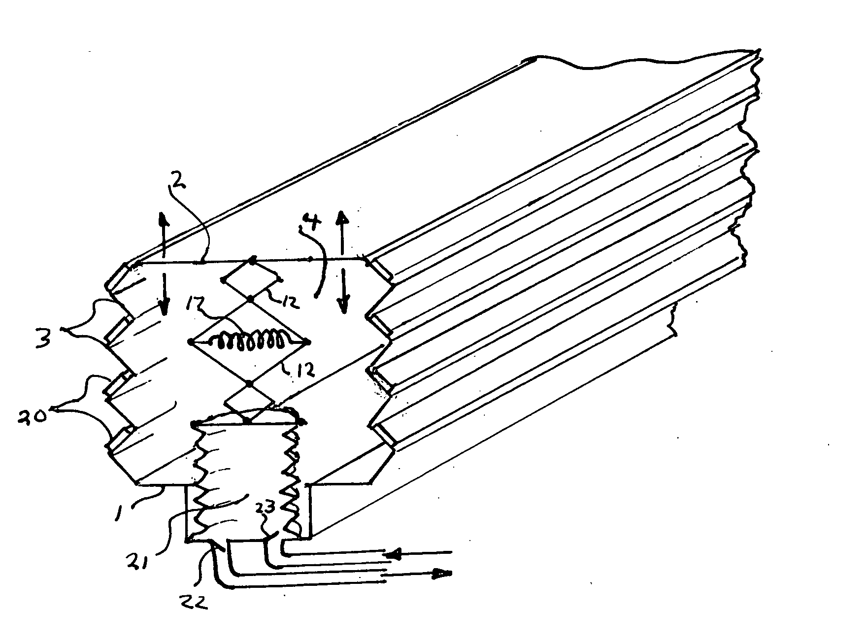
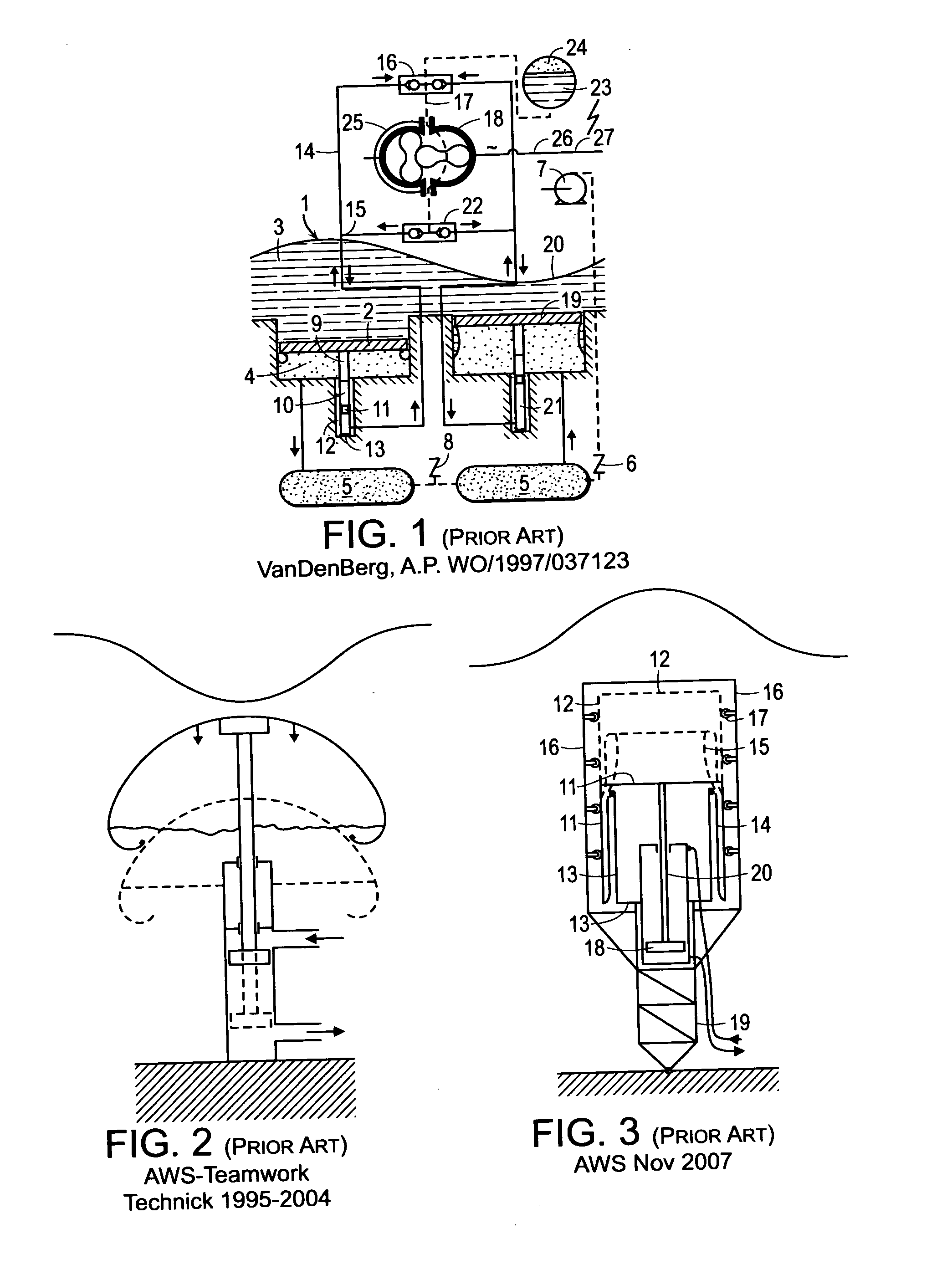
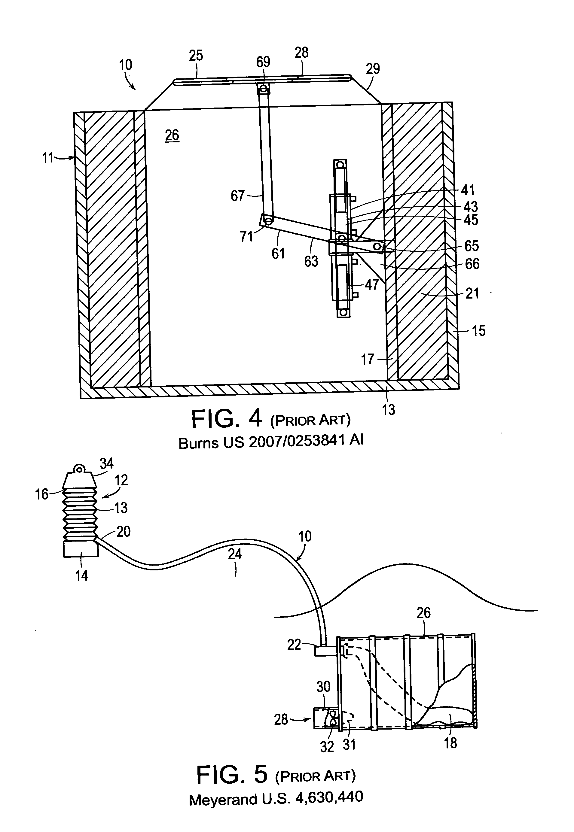
[0054]FIGS. 1-5 show prior art previously discussed herein. It should be noted that any of the embodiments of the present invention of FIGS. 6-18 can use partial evacuation of said containers or surface venting (snorkel vent or bellows) and any of these embodiments can be enhanced by mechanically connected surface floats or buoys. FIG. 6 shows one embodiment of the present invention utilizing a submerged gas tight flexible elastomer impregnated fabric reinforced bellows 3, reinforced against partial internal vacuum and external hydrostatic pressure, affixed and sealed to a movable rigid upper surface 2 slighting below a wave trough 5 and a relatively fixed depth lower surface 1. Surfaces 1, 2 and 3 form a vertical axis gas tight container which can be circular or oblong in planar section. Rigid surfaces 1 and 2 may be fabricated of relatively light weight steel or fiber reinforced plastics (FRP) to maintain low weight and cost. The interior volume 4 of said container is partially ev...


PUM


Abstract

An ocean wave energy device uses large gas filled and surface vented or evacuated flexible containers having rigid movable ends and rigid fixed depth ends connected by flexible bellows, suitably reinforced against external hydrostatic pressure, submerged to a depth below anticipated wave troughs. One or more containers compress and expand as waves and troughs, respectively, pass overhead driving hydraulic or pneumatic, pumping means producing pressurized fluid flow for a common sea bed motor-generator or for other uses or on-board direct drive generators. Mechanical, hydraulic or pneumatic means re-expand said containers when a wave trough is overhead. Power output is augmented by mechanically connecting said rigid moving surfaces to surface floats, which may also provide said surface vent such that as waves lift and troughs lower said floats, said containers are further compressed and re-expanded, respectively. Depth fixing and adjustment means for tides and sea-states are provided.

Description

FIELD OF INVENTION[0001]This invention relates to devices for producing electrical power, pressurized water or other useful work from surface waves on a water body.[0002]More particularly, this invention relates to wave energy converters wherein either all or a substantial portion of the energy captured or produced is from one or more submerged devices relying at least in part on overhead wave induced subsurface differences in hydrostatic pressure which expand and contract or otherwise deform or deflect one or more gas filled submerged containers thereby producing useful work.BACKGROUND OF THE INVENTION[0003]Wave energy commercialization lags well behind wind energy despite the fact that water is several hundred times denser than air and waves remain for days and even weeks after the wind which originally produced them has subsided. Waves, therefore, efficiently store wind kinetic energy at much higher energy densities, typically averaging up to 50 to 100 kw / m of wave front in many ...

Claims


Application Information

Patent Timeline
Patent Type & Authority Applications(United States)
IPC IPC(8): F03B13/18
CPCF03B13/188F03B13/24Y02E10/38F05B2260/406F05B2240/917F03B13/148Y02E10/30
Inventor ROHRER, JOHN W.
Owner ROHRER TECH
Why Eureka
Try Eureka