Flip-flop circuit having scan function

Active Publication Date: 2010-12-09
SAMSUNG ELECTRONICS CO LTD
View PDF8 Cites 37 Cited by
  • Summary
  • Abstract
  • Description
  • Claims
  • Application Information

AI Technical Summary

Benefits of technology

[0010]The present general inventive concept provides a high-speed semi-dynamic flip-flop including a scan function. Embodiments of the present general inventive c

Problems solved by technology

As data speed and volume increase, it becomes challenging to keep power consumption of the semiconductor device low.
Dynamic logic allows a circuit to operate with a higher processing speed, but may also consume more power than a static logic circuit.
H

Method used


Image

  • Flip-flop circuit having scan function
  • Flip-flop circuit having scan function
  • Flip-flop circuit having scan function

Examples


Embodiment Construction

[0046]Preferred embodiments of the general inventive concept will be described below in more detail with reference to the accompanying drawings. The embodiments of the general inventive concept may, however, be embodied in different forms and should not be constructed as limited to the embodiments set forth herein. Rather, these embodiments are provided so that this disclosure will be thorough and complete, and will fully convey the scope of the general inventive concept to those skilled in the art. Like numbers refer to like elements throughout.

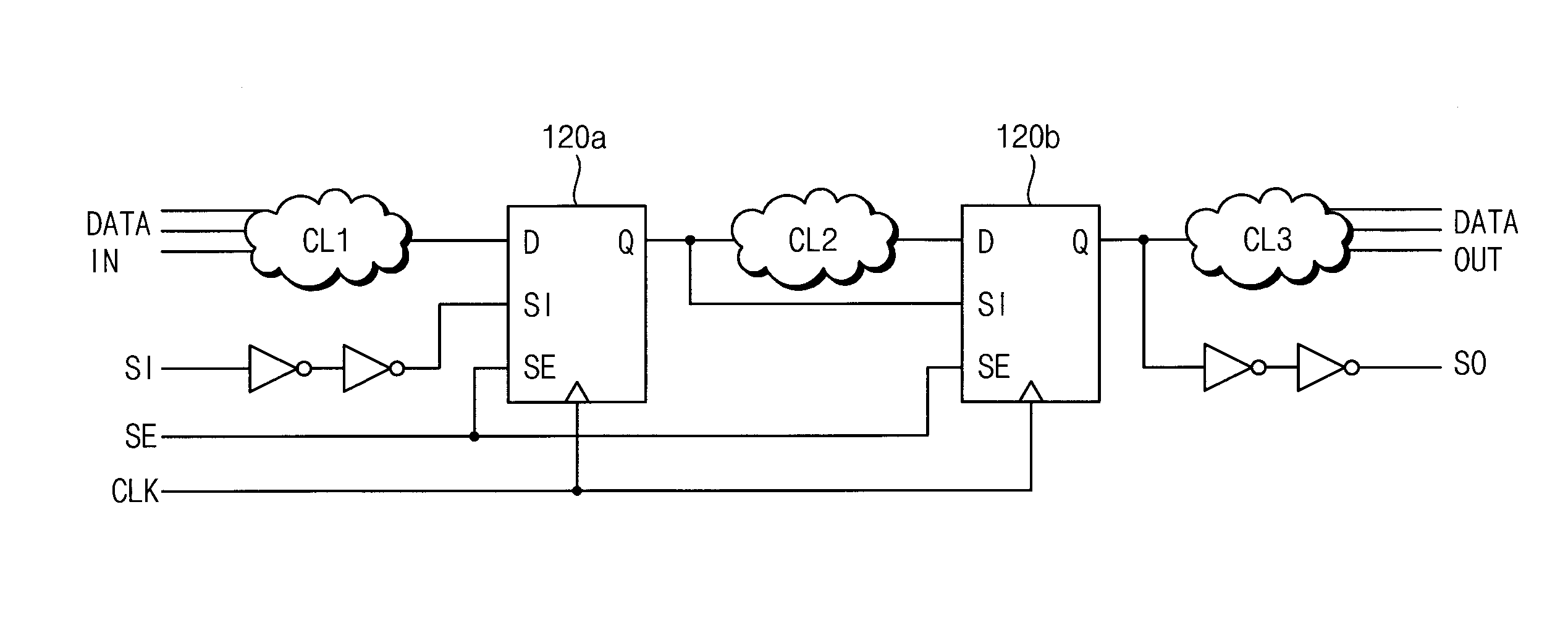
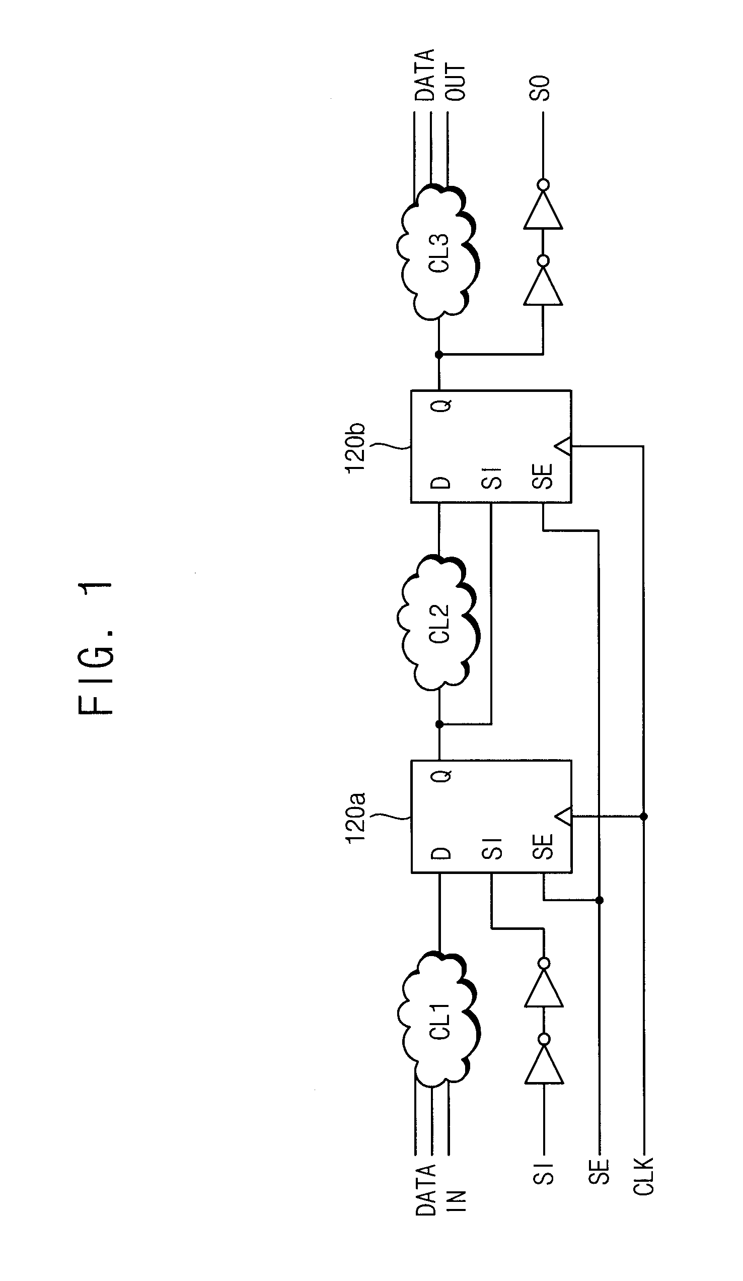
[0047]An example of a scan-capable flip-flop circuit is illustrated in FIG. 1.

[0048]A plurality of MUX flip-flop registers 120 are connected in series. The flip-flops 120a and 120b have inputs D and outputs Q connected to circuit logic CL1, CL2, and CL3. The circuit logic CL1 located at an input of the first flip-flop 120a receives data in and outputs an output signal to the input D of the flip-flop 120a that corresponds to the input data an...


PUM


Abstract

A flip-flop circuit having a scan function includes an internal clock generator to receive a clock signal, a scan enable signal, and a first input signal, and to output an internal timing signal based on each of the clock signal, the scan enable signal, and the first input signal. The circuit includes a dynamic input unit to receive a second input signal, the scan enable signal, a first timing signal, and the internal timing signal, and to output a first output signal. The circuit also includes a static output unit to receive the first timing signal and the first output signal and to output a static output signal, and the dynamic input unit outputs the first output signal corresponding to one of the first input signal and the second input signal, respectively, based on a status of the scan enable signal.

Description

CROSS-REFERENCE TO RELATED APPLICATIONS[0001]This U.S. non-provisional patent application claims priority under 35 U.S.C. §119 of Korean Patent Application No. 10-2009-0050999, filed on Jun. 9, 2009, the entire contents of which are hereby incorporated by reference in its entirety.BACKGROUND[0002]1. Field of the Invention[0003]The present disclosure herein relates to digital signal processing, and more particularly, to a flip-flop circuit having a scan function.[0004]2. Description of the Related Art[0005]Semiconductor devices, and processors in particular, continue to decrease in size relative to the amount of data processed. As data speed and volume increase, it becomes challenging to keep power consumption of the semiconductor device low.[0006]High-performance circuits may utilize dynamic circuitry to increase processing speed. System clocks have jitter, or variations in high or low levels, especially during rising and falling edges of the clock signal. While static circuitry may...

Claims


Application Information

Patent Timeline
IPC IPC(8): H03K19/173H03K3/356
CPCH03K3/356191G01R31/318541
Inventor LEE, HYOUNG WOOKKIM, MIN-SU
Owner SAMSUNG ELECTRONICS CO LTD
Why Eureka
Try Eureka